Michelson interferometer based delay line interferometers

a delay line and interferometer technology, applied in optics, instruments, electrical equipment, etc., can solve the problems of difficult and expensive, interference between beams from the two channels, and low or high coefficient of thermal expansion

Inactive Publication Date: 2007-03-29
OPTOPLEX CORP
View PDF4 Cites 17 Cited by
  • Summary
  • Abstract
  • Description
  • Claims
  • Application Information

AI Technical Summary

Benefits of technology

[0014] In specific embodiments of the interferometer, the means for recombining can comprise a first reflector positioned to reflect the first beam, and the means for recombining can further comprise a second reflector positioned to reflect the second beam. In this embodiment, one of the reflectors is separated from the splitting location by a distance sufficient to make the difference in

Problems solved by technology

After the recombination, the beams from the two channels interfere constructively or destructiv

Method used


Image

  • Michelson interferometer based delay line interferometers
  • Michelson interferometer based delay line interferometers
  • Michelson interferometer based delay line interferometers

Examples


Embodiment Construction

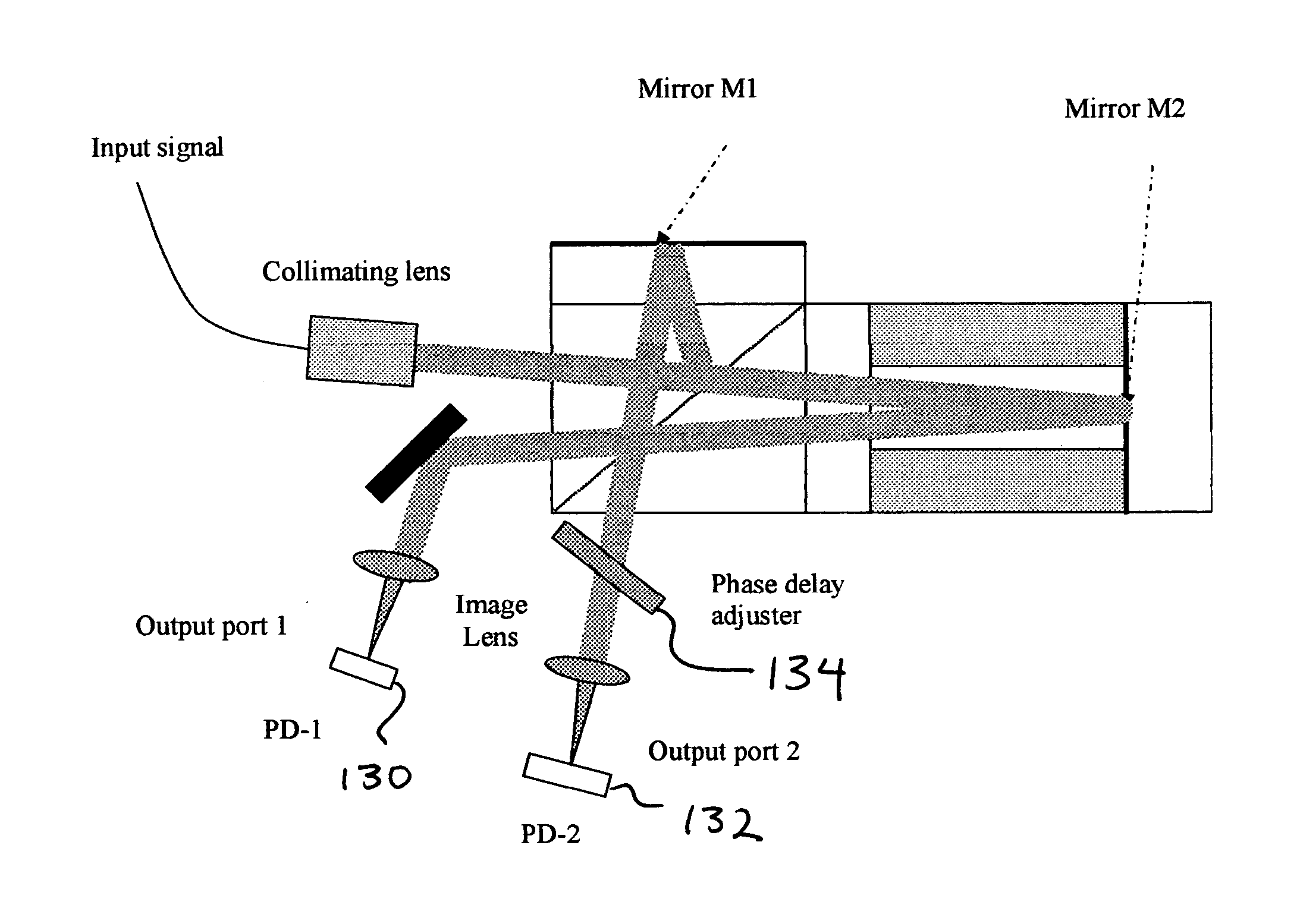
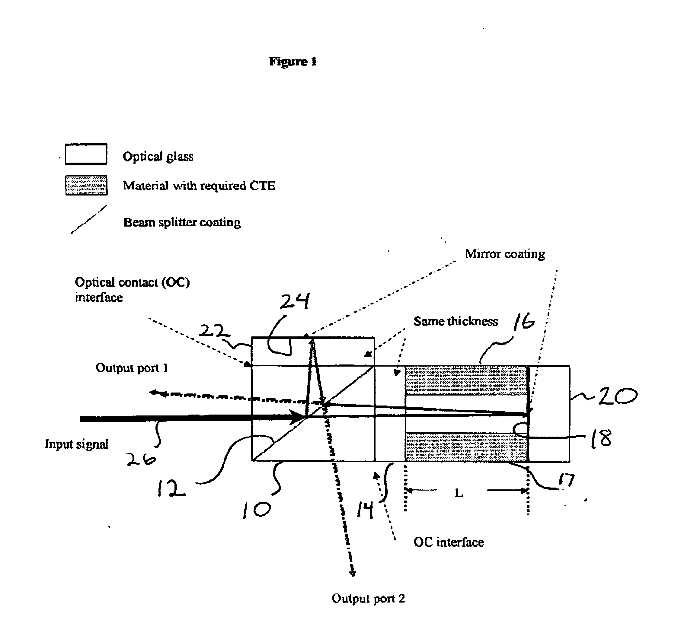
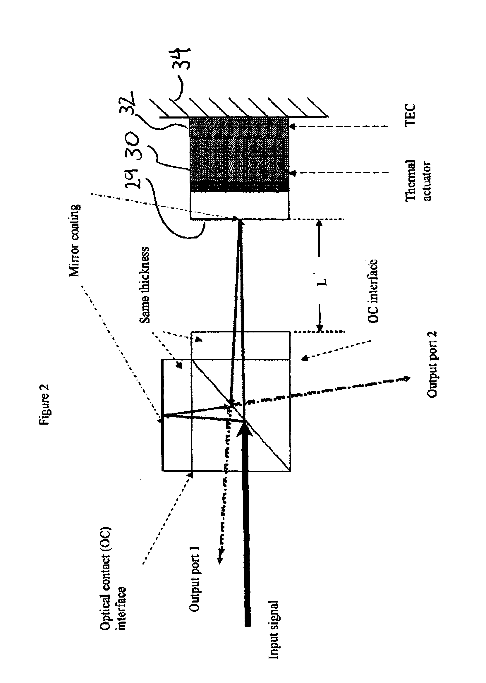
[0031] An embodiment of the present invention is illustrated in FIG. 1, which shows a Michelson-based delay line interferometer (DLI) formed by a beamsplitter 10 with beamsplitting coating 12 An optical glass element 14 is affixed to the right hand side of the beamsplitter. Element 14 can be affixed, e.g., with an index matching adhesive as known in the art. Spacers 16 and 17, having a length L, and made of a material having a low coefficient of thermal expansion (CTE), are affixed to the right hand side of the optical element 14. To the right hand side of the spacers is a mirror coating 18 on a substrate 20. A second optical glass element 22 is affixed to the top of beamsplitter 10. A mirror (reflective) coating 24 is located on the second surface of element 22. When elements 14 and 22 are of the same material and thickness, the round-trip optical path length difference (OPD) between mirror coating 18 and mirror coating 24 is 2 times L, where L is the length of the spacer 16. The i...


PUM


Abstract

An interferometer includes a means for splitting, at a splitting location, an input light beam into a first beam and a second beam; and means for recombining, at a recombination location, the first beam and the second beam. The interferometer is designed such that the first beam will travel a first optical path length (OPL) from the splitting location to the recombination location, and the second beam will travel a second OPL from the splitting location to the recombination location and such that when the input light beam has been modulated at a data rate comprising a time interval, then the difference in optical path lengths between the first OPL and the second OPL is about equal to the time interval multiplied by the speed of light.

Description

[0001] This application also claims priority to U.S. Provisional Patent Application Ser. No. 60 / 698,584, filed Jul. 11, 2005, titled: “Integration of Michelson Differential Phase Shift Keying (DPSK) Demodulator with Photo Detector,” incorporated herein by reference. This application also claims priority to U.S. Provisional Patent Application Ser. No. 60 / 748,096, filed Dec. 5, 2005, titled: “Co-package DQPSK Demodulator by Michelson Interferometer,” incorporated herein by reference. This application also claims priority to U.S. Provisional Patent Application Ser. No. 60 / 786,630, filed Mar. 27, 2006, titled: “Free-Space Optical Hybrid,” incorporated herein by reference. This is a continuation-in-part of U.S. patent application Ser. No. 10 / 796,512, filed Mar. 8, 2004, titled: “Unpolarized Beam Splitter Having Polarization-Independent Phase Difference When Used As An Interferometer,” incorporated herein by reference. This is a continuation-in-part of U.S. patent application Ser. No. 11 / ...

Claims


Application Information

Patent Timeline
IPC IPC(8): G02B27/00
CPCH04B10/677
Inventor HSIEH, YUNG-CHIEH
Owner OPTOPLEX CORP
Why Eureka
Try Eureka