Heaphone with behind-the-head headband

a headband and headphone technology, applied in the direction of supra/circum aural earpieces, headphones for stereophonic communication, sound producing devices, etc., can solve the problems of poor acoustics, inability to wear spectacles and a headphone, and reduce the comfort of wearing, so as to achieve the effect of minimal contact pressure of the transducer

Inactive Publication Date: 2007-03-29
SENNHEISER ELECTRONICS GMBH & CO KG
View PDF7 Cites 18 Cited by
  • Summary
  • Abstract
  • Description
  • Claims
  • Application Information

AI Technical Summary

Benefits of technology

[0008] Therefore the primary object of the present invention is to provide a headphone with a behind-the-head headband, which can adapt to different head and ear shapes and in that case guarantees a minimum contact pressure of the transducers against the ears of the wearer.
[0011] The possibility of adjustment of the spacing with respect to the contact location means that the transducer can be positioned exactly over the auditory channel of the headphone wearer without pressure points on the ear.
[0012] In accordance with an aspect of the present invention, the transducer is adapted to be pivotable about the behind-the-head headband whereby it is possible to set a suitable angle between transducer and temples of the headphone wearer so that the transducer can be adapted to different ear shapes of the headphone wearer. That contributes considerably to an improved contact pressure and thus improved acoustics for the headphone.
[0015] In accordance with a further preferred aspect of the present invention, the second portion is designed to be inclined inwardly. If now the headphone with the behind-the-head headband is to be adapted to the corresponding shape of the head of the wearer of the headphone, the transducer is held stationarily over the auditory passage of the headphone wearer and the spacing between the first or second contact location and the transducer is altered. That is effected by the contact locations being pressed against the head of the headphone wearer upon an increase in the spacing between the contact location and the transducer. In that way contact pressure can be obtained both at the temple of the wearer and also between the transducer and the ear, and can be mutually matched.
[0017] In accordance with a further aspect of the present invention, the transducer has a self-locking arresting means. That, therefore, prevents the transducer from being accidentally displaced in respect of its position relative to the contact location.

Problems solved by technology

In addition, the fact that the band 100 or the behind-the-ear hook rests directly on the root of the ear is found to be disadvantageous as perspiration and pressure points are quickly formed there, in particular at elevated temperatures, so that this involves a reduced level of wearing comfort.
Furthermore, that arrangement is found to be disadvantageous particularly for people who wear spectacles, as spectacles generally also rest on the root of the ear so that it is not possible to wear spectacles and a headphone of that kind at the same time.
As that arrangement does not provide that the transducers are directly pressed against the ears of the person wearing the headphone, only poor acoustics can be achieved.
In that case the behind-the-head headband is designed to be adjustable in length so that approximate adaptation to the corresponding head of the headphone wearer is possible, but that arrangement does not guarantee optimum contact pressure for the transducer.

Method used


Image

  • Heaphone with behind-the-head headband
  • Heaphone with behind-the-head headband
  • Heaphone with behind-the-head headband

Examples


Embodiment Construction

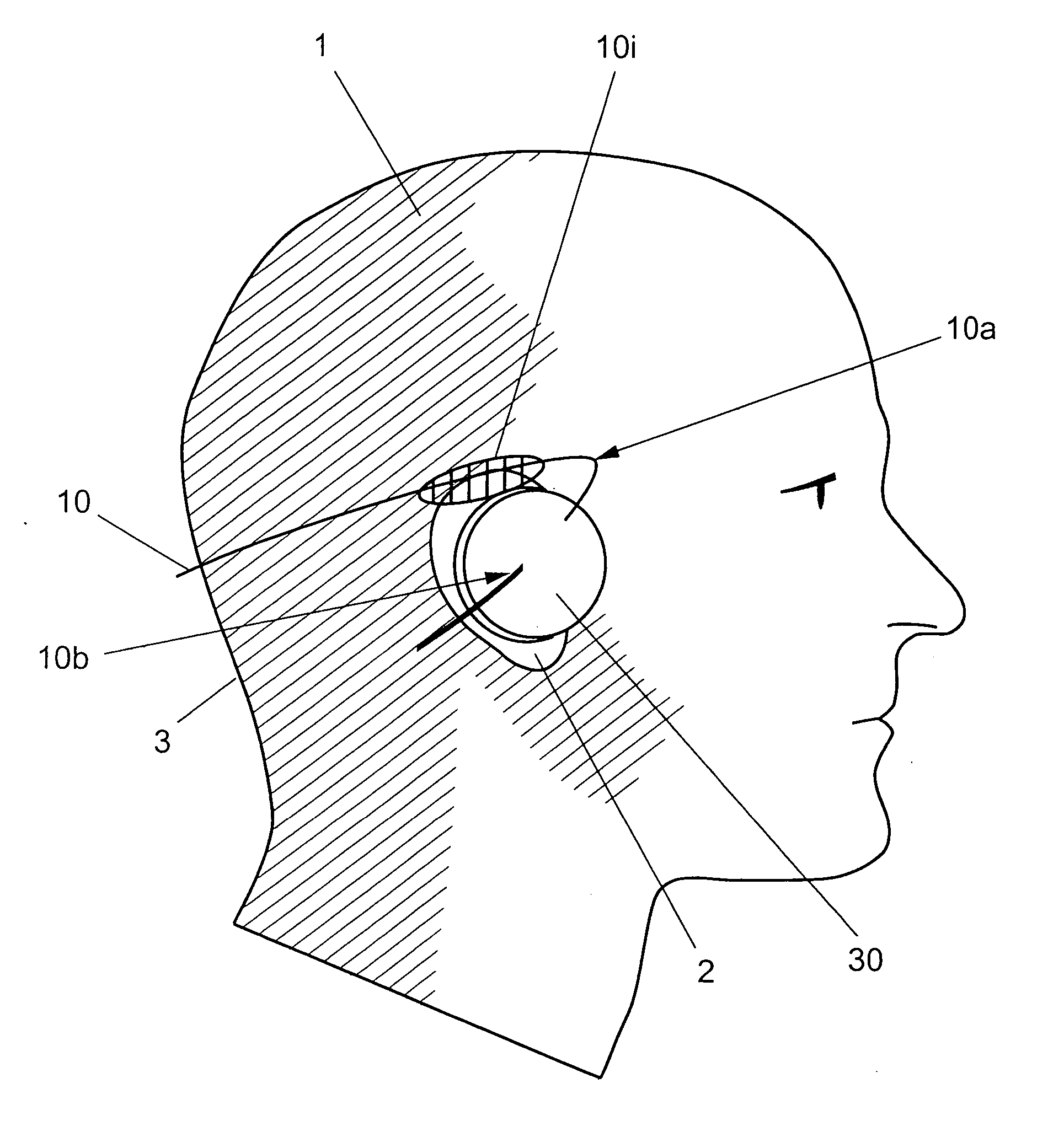
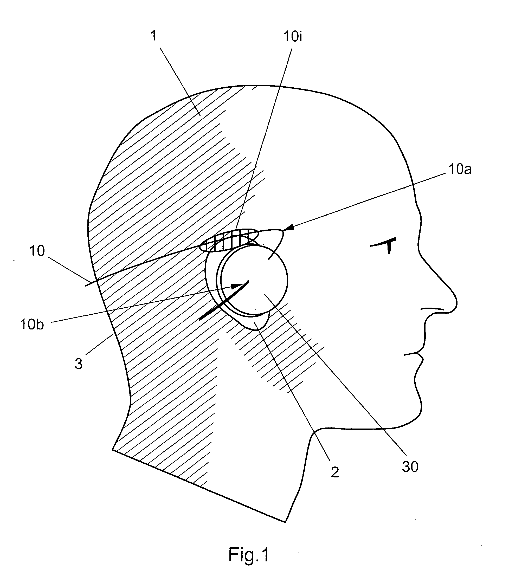
[0031]FIG. 1 shows a side view of a headphone wearer 1 and a headphone with a behind-the-head headband according to the invention. In this case the figure shows in particular the head 1, an ear 2 as well as the back of the head 3 of a headphone wearer. The headphone according to the invention comprises a behind-the-head headband 10 and a transducer 30 fixed to the behind-the-head headband 10. The behind-the-head headband substantially comprises a first and a second portion 10, 10b which meet at a location 10a which represents an angle configuration. In other words, the behind-the-head headband has a first portion which extends in a substantially horseshoe shape around the back of the head of the headphone wearer. In that case the second portion 10b is arranged at a predetermined angle relative to the first portion, that is to say the second portion 10b is bent around the angle configuration 10a. In this arrangement the transducer 30 is arranged at the second portion 10b of the behin...


PUM


Abstract

There is provided a headphone with a behind-the-head headband comprising at least one transducer and a behind-the-head headband for receiving the transducer. The behind-the-head headband further comprises first and second contact locations for resting against a temporal bone of a wearer of the headphone. The spacing between the transducer and the first or second contact location can be adjusted. By virtue of the possibility of adjusting the spacing with respect to the contact location the transducer can be positioned exactly over the auditory channel of the headphone wearer without pressure points on the ear.

Description

CROSS-REFERENCE TO RELATED APPLICATION [0001] This application claims priority of International Application No. PCT / EP2004 / 010039, filed Sep. 9, 2004 and German Application No. 103 42 532.2, filed Sep. 12, 2003, the complete disclosures of which are hereby incorporated by reference.BACKGROUND OF THE INVENTION [0002] a) Field of the Invention [0003] The invention concerns a headphone with behind-the-head headband. Headphones with behind-the-head headbands represent headphones in which the headphone band is not worn on the head but at the back of the head. [0004] b) Description of the Related Art [0005] As state of the art, attention is directed in this matter to DE 198 10 582 A1. [0006] As diagrammatically illustrated in FIG. 5, a transducer 300 is hooked in position on the ear so that the band 100 or the behind-the-ear hook rests on the junction root of the ear. In that arrangement, the nape-of-the-neck band 100 stands away in the region of the nape of the neck as, if it were in con...

Claims


Application Information

Patent Timeline
Patent Type & Authority Applications(United States)
IPC IPC(8): H04R25/00H04R1/10H04R5/033
CPCH04R1/1008H04R5/0335H04R1/1066
Inventor MILDE, LARS
Owner SENNHEISER ELECTRONICS GMBH & CO KG
Why Eureka
Try Eureka