Apparatus and Method for Control of Refractive Index Changes in a Material

Inactive Publication Date: 2012-09-27
TECHNOLAS PERFECT VISION
View PDF16 Cites 13 Cited by
  • Summary
  • Abstract
  • Description
  • Claims
  • Application Information

AI Technical Summary

Benefits of technology

[0007]In accordance with the present invention, a system and method are provided for stabilizing an eye which require physically restraining movements of an eye in orthogonal x-y-z directions. The essential purpose here is to stabilize the eye, or some other transparent object made of a resilient material, while preventing any distortion of the eye (object) that will substantially change its refraction or refractive properties. For the present invention, this is done by juxtaposing the contact surface of a contact element against a selected surface of the eye (object) and establishing an operational location for the contact element relative to the eye. More specifically, with the contact element in its operational location there will be minimal, if any, contact pressure on the eye and, thus, unwanted distortions of the eye are effectively obviated.
[0013]As an added feature of the present invention, a liquid can be deposited on the selected surface of the eye (object) prior to a juxtaposition of the contact element with the selected surface. Specifically, this can be done to buffer the interaction between the contact element and the object and further to equalize the pressure exerted by the contact element on the eye.

Problems solved by technology

Anatomical characteristics of the eye, however, can undermine the effectiveness of any laser procedure.
These wrinkles can then cause an undesirable refraction, dispersion and degradation of the laser beam, as well as other adverse optical effects, as it passes through the cornea.
An additional drawback caused by dispersion of the laser beam is the possibility of unintentionally damaging non-targeted tissue.

Method used


Image

  • Apparatus and Method for Control of Refractive Index Changes in a Material
  • Apparatus and Method for Control of Refractive Index Changes in a Material
  • Apparatus and Method for Control of Refractive Index Changes in a Material

Examples


Embodiment Construction

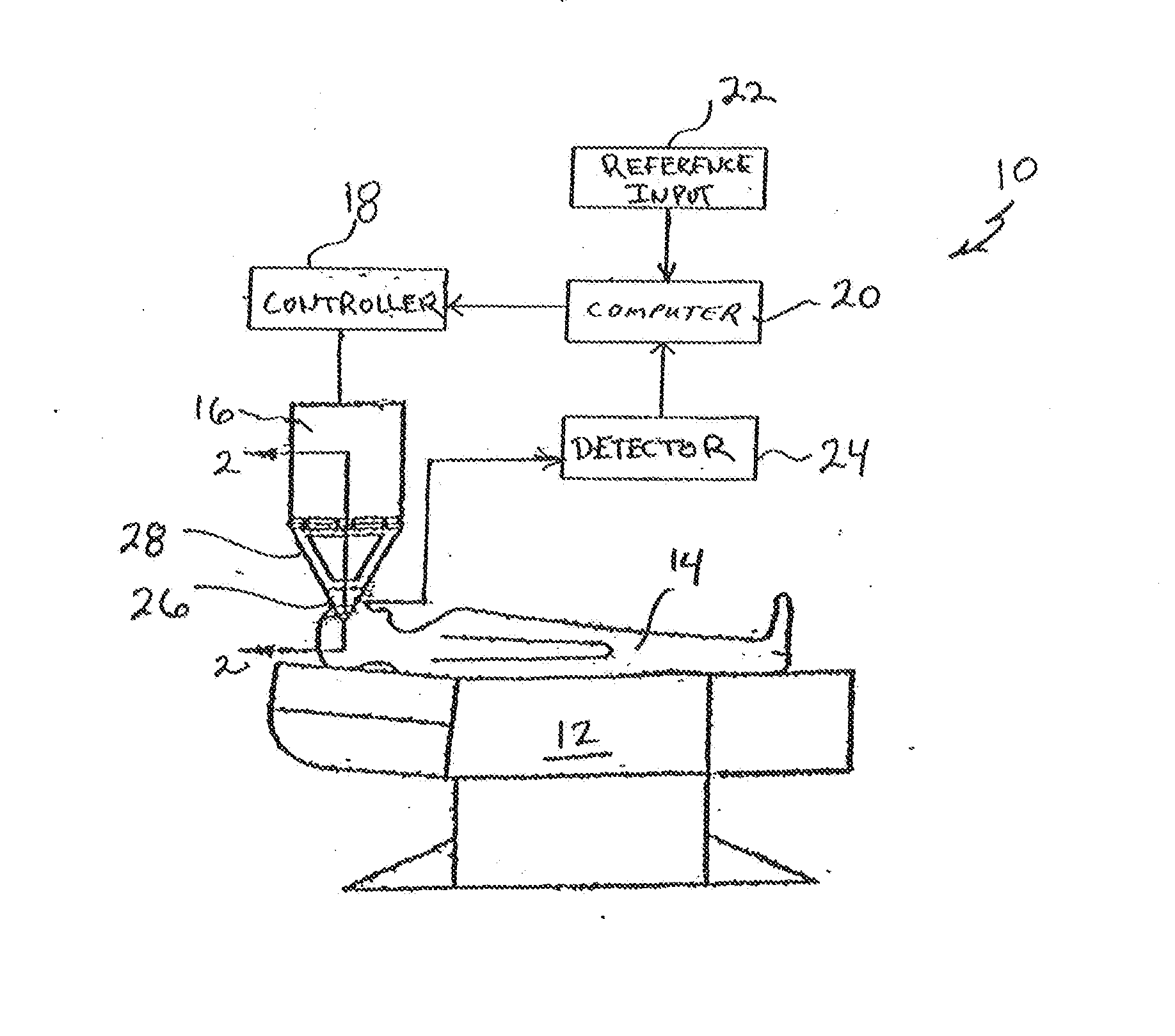
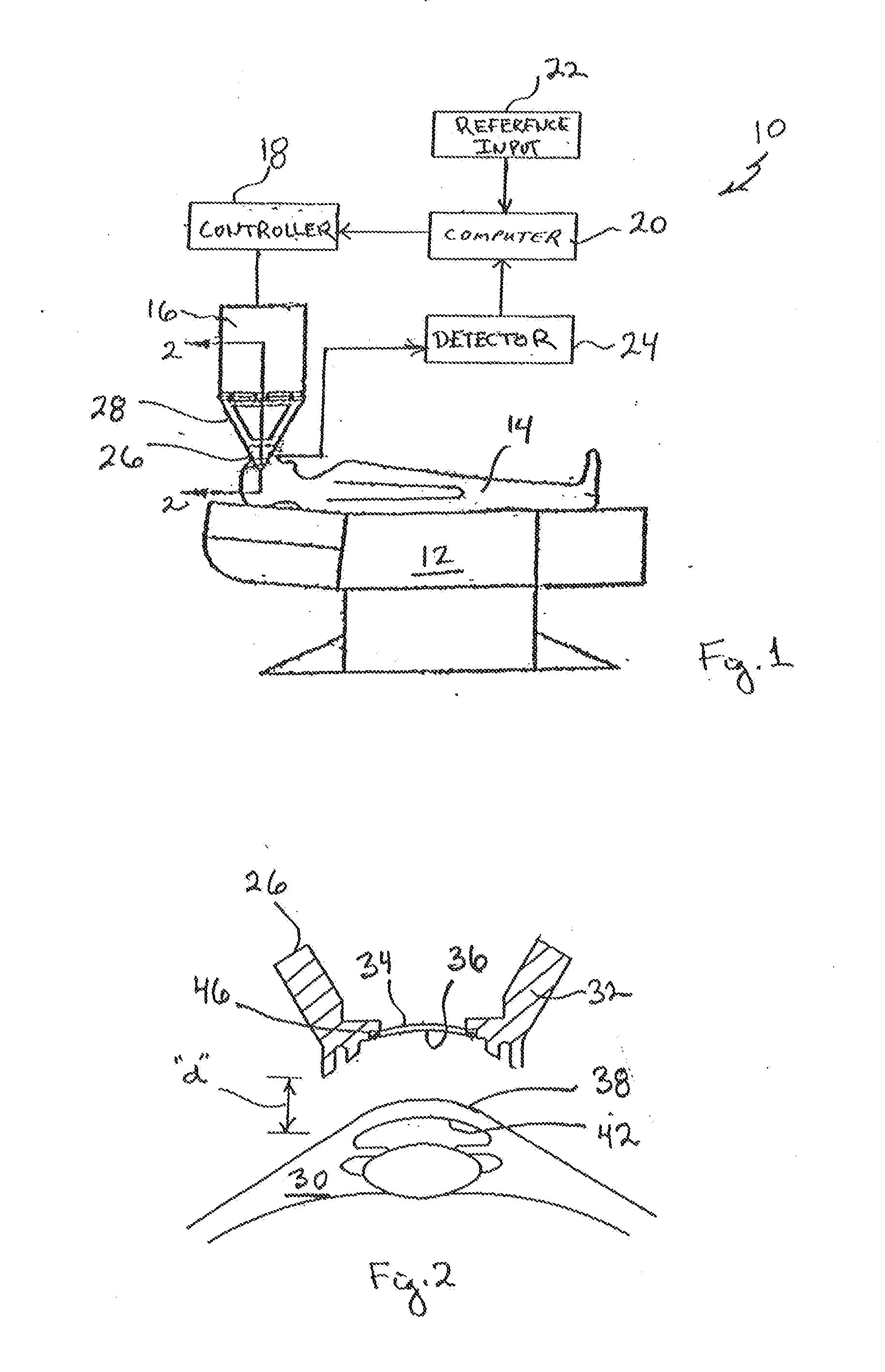
[0019]Referring initially to FIG. 1, a system for minimizing refractive index change in an eye (work piece) during an ophthalmic laser surgical procedure (alteration of the work piece) is shown and is generally designated 10. As shown, the system 10 includes a table (chair) 12 for supporting a patient 14 during an ophthalmic surgical laser procedure. The system 10 also includes a laser unit 16 for performing the surgical laser procedure. Further, system 10 includes a controller 18 for operating the laser unit 16, and it includes a computer 20 that provides instructions for an operation of the controller 18.

[0020]FIG. 1 also indicates that the computer 20 functions in response to a reference input 22, and that the computer 20 also receives input from a detector 24. More specifically, the detector 24 provides information to the computer 20 that pertains to the interactive relationship between a contact element 26 and the patient 14. In particular, this interactive relationship is moni...


PUM


Abstract

A system and method for stabilizing an eye includes a contact element that is placed in contact with the anterior surface of the eye. The purpose here is to oppose movements of the eye during an ophthalmic surgical procedure. Importantly, while it is in contact with the eye, the contact element is positioned to exert minimal pressure on the eye. This is done to avoid causing any deformations of the eye that might otherwise adversely compromise a laser beam during the ophthalmic surgery.

Description

[0001]This application claims the benefit of U.S. Provisional Patent Application Ser. No. 61 / 467,263, filed Mar. 24, 2011.FIELD OF THE INVENTION[0002]The present invention pertains generally to systems and methods for performing ophthalmic surgery. More particularly, the present invention pertains to systems and methods for stabilizing an eye during ophthalmic surgery. The present invention is particularly, but not exclusively, useful as a system and method that stabilizes the eye with a contact element while causing minimal changes in refractive properties of the eye during ophthalmic surgery.BACKGROUND OF THE INVENTION[0003]Surgical lasers are now commonly used in a variety of ophthalmic surgical procedures, including the treatment of ocular diseases and the correction of optical deficiencies. In these procedures, the surgical laser is often chosen as the tool of choice because of the ability of the laser to be accurately focused with great precision. In addition, the ability of t...

Claims


Application Information

Patent Timeline
IPC IPC(8): A61G15/00G02B7/02
CPCA61F9/009A61F2009/00851A61F2009/00844
Inventor KANDULLA, JOCHEN
Owner TECHNOLAS PERFECT VISION
Why Eureka
Try Eureka