
Method and apparatus for diffusion bonding, brazing and joining

Active Publication Date: 2007-02-22
THE BOEING CO
View PDF1 Cites 3 Cited by
  • Summary
  • Abstract
  • Description
  • Claims
  • Application Information

AI Technical Summary

Benefits of technology

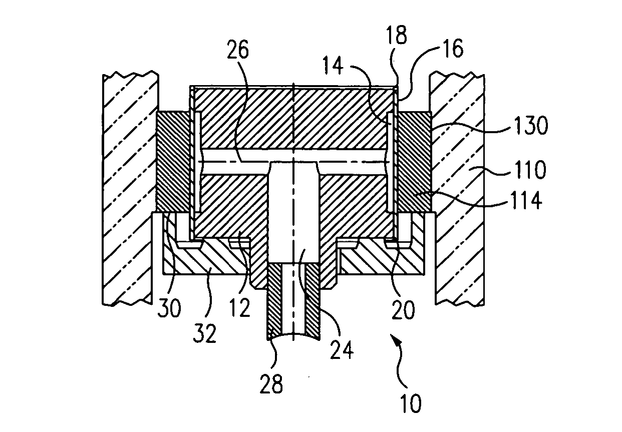
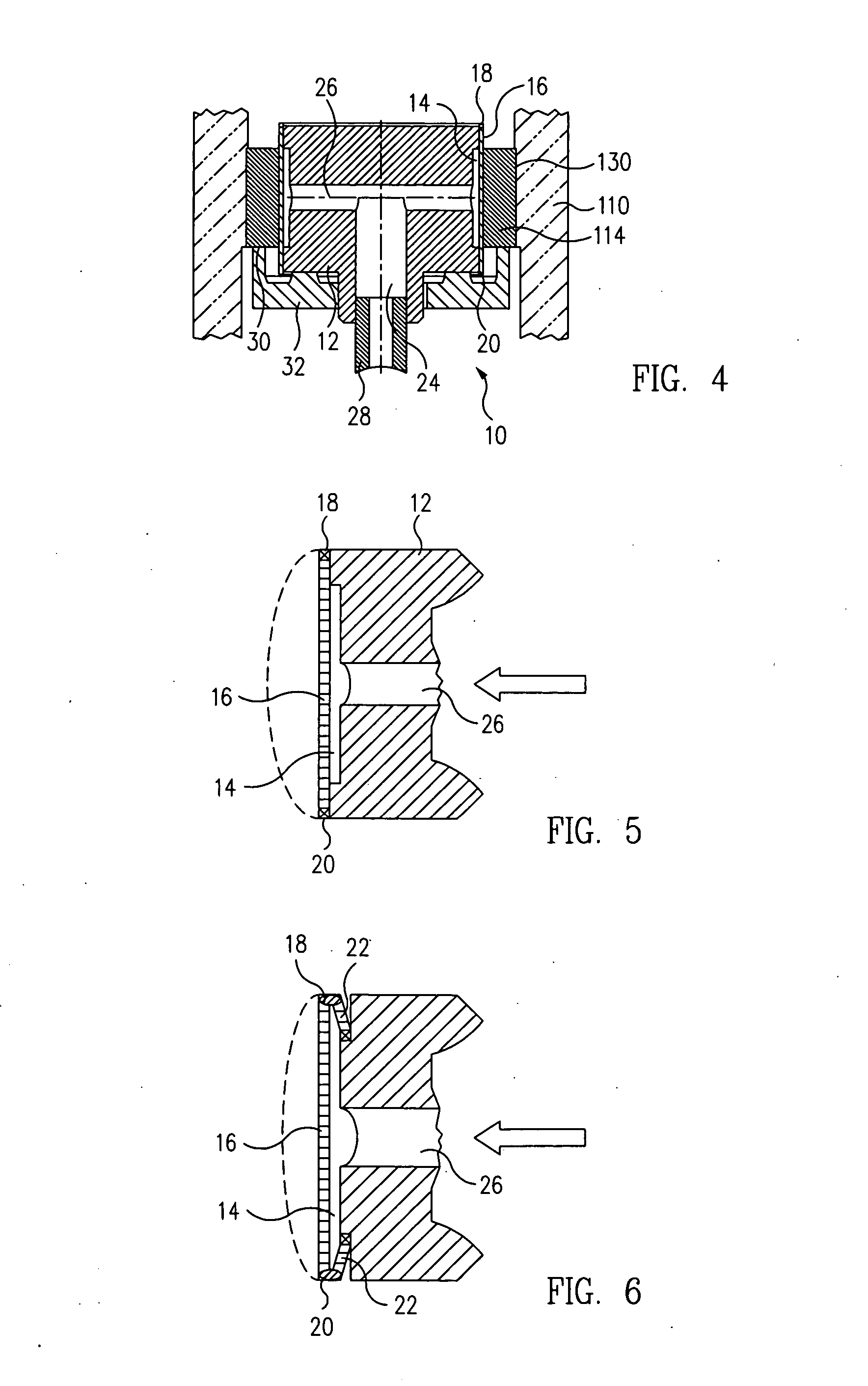
[0009] A radial flange can be disposed at the lower end of the body and arranged to contact a lower end of the first annular cylinder, and thereby position the cylinder such that it is axially centered with respect to the annular membrane. Means can also be provided for limiting the axial depth to which the cylindrical body and apparatus can be inserted into the second annular cylinder, such as an axial protrusion on the upper end of the cylindrical body that contacts an upper end of the second annular cylinder when the first cylinder is located at the desired axial bonding position. Additionally, means can be provided for equalizing the pressure between the upper and lower ends of the first cylindrical body when the body is axially inserted into or removed from the second annular cylinder.

Problems solved by technology

However, due to their particular nature, Stirling engines also include certain drawbacks, among which is that they require both input and output heat exchangers, the efficiency of which must be optimized with some care to achieve maximum engine effectiveness.

Method used


Image

  • Method and apparatus for diffusion bonding, brazing and joining
  • Method and apparatus for diffusion bonding, brazing and joining
  • Method and apparatus for diffusion bonding, brazing and joining

Examples


Embodiment Construction

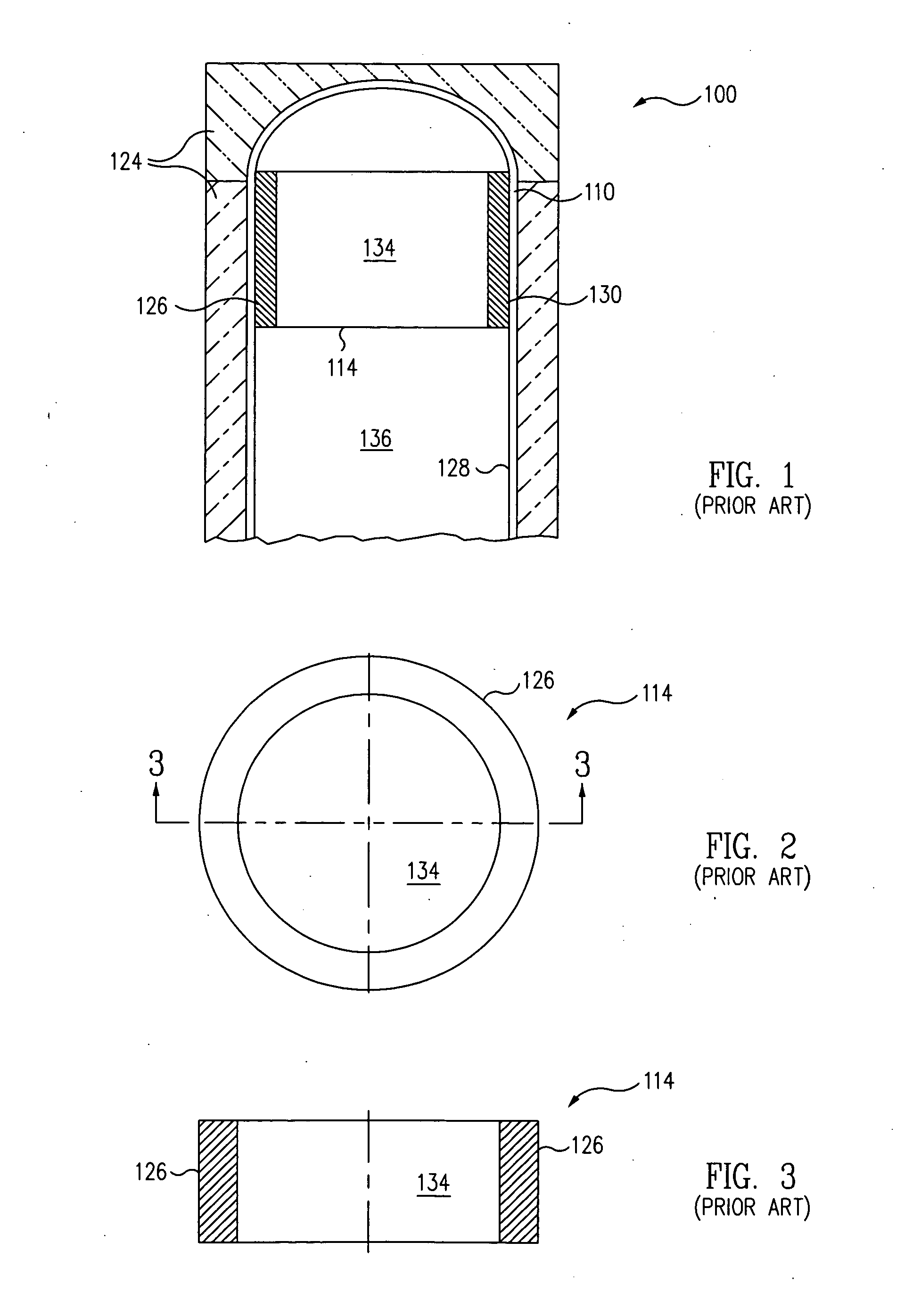
[0025] In FIG. 1, a heater head portion 110 of a Stirling engine 100, showing the head encased within a heat jacket 124, and an annular “acceptor” or heat exchanger 114, having an exterior sidewall 126 bonded to an interior sidewall 128 of the heater head in the upper end portion thereof, is illustrated in the partial cross-sectional elevation view. It may be noted that the heat exchanger generally corresponds to a first, open-ended tube, or annular cylinder, and the heater head corresponds to a second, closed-ended tube, or annular cylinder. Thus, in a more generalized sense one aspect of, the present invention provides methods and apparatus for effecting a reliable, void-free bond, i.e., a diffusion-bonded or brazed joint 130 between the exterior wall of a first annular cylinder and the interior wall of a concentric second annular cylinder.

[0026] An enlarged end view and a cross-sectional elevation view of the heat exchanger 114 are illustrated in FIGS. 2 and 3, respectively. Wit...


PUM

PropertyMeasurementUnit
Temperatureaaaaaaaaaa
Fractionaaaaaaaaaa

Abstract

Apparatus for diffusion bonding, brazing, or joining between respective surfaces of two parts, e.g., the exterior wall of a first annular cylinder and the interior wall of a concentric second annular cylinder, includes a cylindrical body having a circumferential cavity positioned between upper and lower ends thereof. A flexible annular membrane is disposed concentrically over the cavity, and respective upper and lower ends of the membrane are each sealingly hinged to the body. The body is assembled coaxially within the first cylinder, and the assembly then inserted coaxially into the second cylinder to the desired axial bonding position. The cavity is pressurized, causing the membrane, and responsively, the first cylinder, to expand radially within the second cylinder. The temperature of the parts is then raised and maintained for a selected period of time to bond the respective walls of the two cylinders to each other.

Description

TECHNICAL FIELD [0001] This invention relates to manufacturing tooling and processes in general, and in particular, to a method and apparatus for effecting a reliable, void-free diffusion bond or brazed joint between the surfaces of two parts, for example, the exterior wall of a first annular cylinder and the interior wall of a concentric second annular cylinder. BACKGROUND [0002] The need to bond the respective curved or flat planar surfaces of two parts together occurs frequently in many and diverse manufacturing areas, and arises independently of the type of materials involved or the particular application at hand. For example in the case of a Stirling engine, it is desirable to effect a virtually void-free bonding joint between the annular “acceptor” or heat exchanger, of the engine and the upper end of the “heater head” cylinder. [0003] The Stirling engine was developed in England in about 1816 as a safer alternative to the steam engines of the time, and operates by alternately...

Claims


Application Information

Patent Timeline
IPC IPC(8): B23K31/02B21D39/00
CPCB23K1/0008B23K2201/06B23K20/023B23K2101/06
Inventor KAYSER, GREGORY F.WISNER, DANIEL L.SOMERVILLE, JOHN G.FERRIN, JONATHAN H.
Owner THE BOEING CO
Learn More