Method and valve assembly for flushing of debris

Active Publication Date: 2018-02-22
FMC KONGSBERG SUS
View PDF1 Cites 0 Cited by
  • Summary
  • Abstract
  • Description
  • Claims
  • Application Information

AI Technical Summary

Benefits of technology

The invention offers a method and arrangement for self-cleaning a clogged valve assembly that prevents permanent clogging. It works autonomously without requiring an external control system. Additionally, it reduces the risk of cavitation and erosion inside the valve, which can degrade its integrity and lead to leaks of toxic or environmentally harmful fluids. Finally, the invention can be equipped with a control system to override its working principles in certain modes of operation.

Problems solved by technology

With all chemical injection valves and other small sized valves that have a restricted fluid passage there is a risk of debris getting caught in the fluid passage and clogging the fluid passage.
Such control systems are vulnerable to clogging themselves because they usually involve small apertures that measure the flow by differential pressure.
This prior art flushing system is relatively complex and the use of such a flushing system adds a vulnerability to the working of the valve arrangement, as the flushing of the clogged valves depend on the proper working of the valve arrangement.
The use of the prior art flushing system causes a reduced flow rate due to the size of the measurement apparatus for monitoring the flow.

Method used


Image

  • Method and valve assembly for flushing of debris
  • Method and valve assembly for flushing of debris
  • Method and valve assembly for flushing of debris

Examples


Embodiment Construction

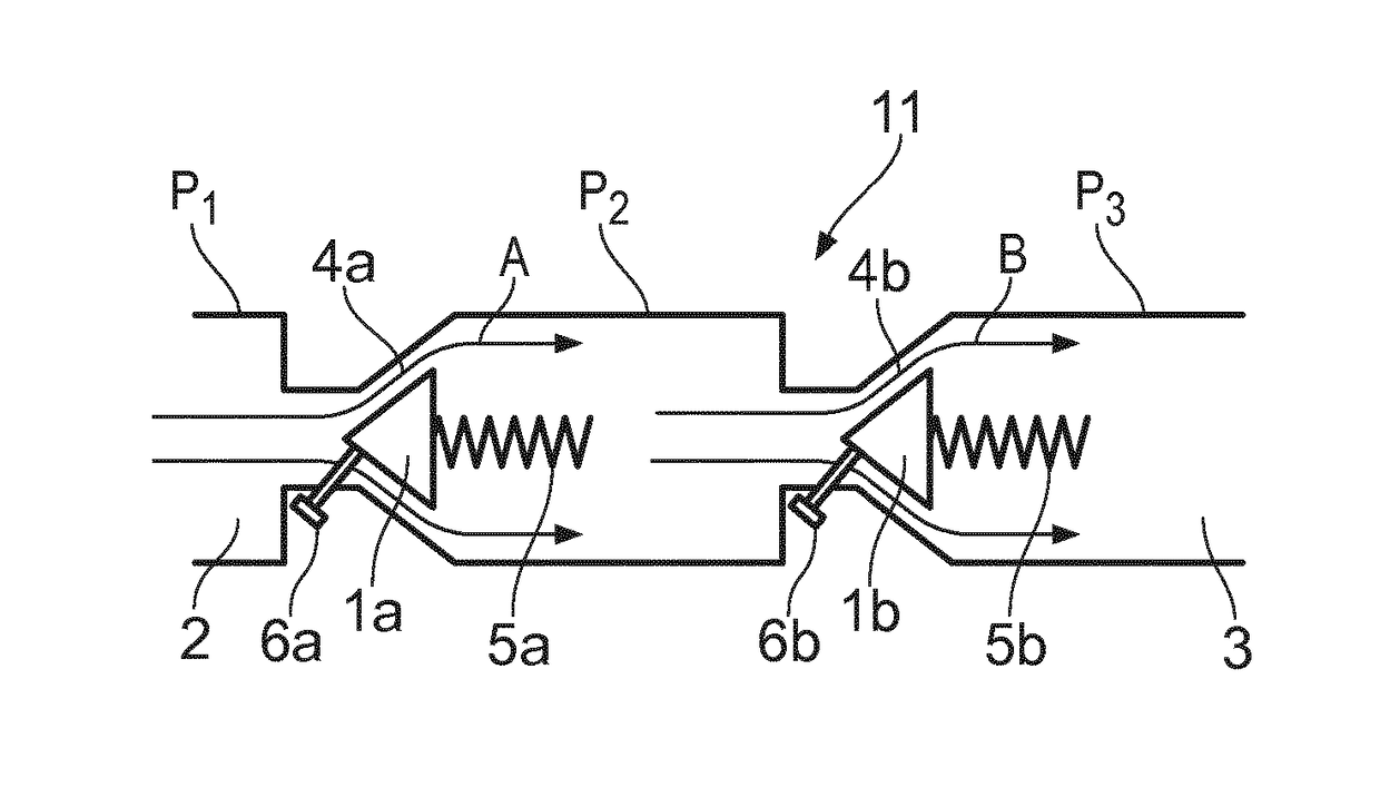
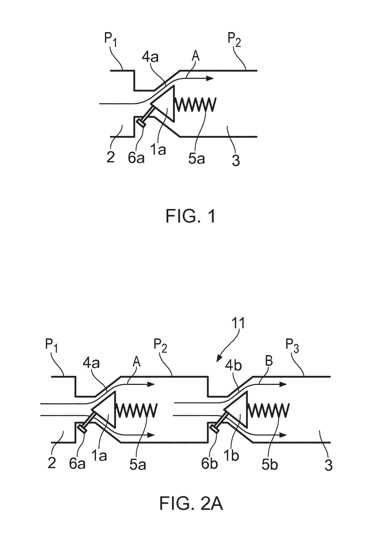
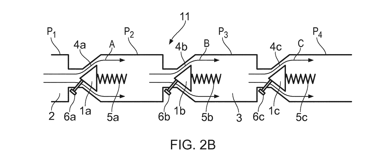
[0056]A prior art flow regulating unit is shown in FIG. 1. The flow regulating unit 1a has an inlet 2, here shown as an inlet channel, with an inlet pressure P1 and an outlet 3, here show as an outlet channel, with an outlet pressure P2. The flow regulating unit 1a is arranged with an opening 4a for regulating a flow A into the outlet 3 (which may be connected to a well or a well area connected to the well). The inlet pressure is larger than the outlet pressure, thus providing a pressure drop over the flow regulating unit 1a. The flow regulating unit 1a is arranged with a spring element 5a to regulate the opening 4a in response to the pressure difference over the flow regulating unit 1a. The spring element 5a is set to resist compression in accordance with the pressure difference occurring during normal fluid flow through the opening 4a.

[0057]As the skilled person will realize, a preloading arrangement capable of providing resistance until a certain pressure level is obtained and t...


PUM


Abstract

The invention concerns a method for flushing of debris from a valve assembly arranged in a fluid line. The valve assembly comprises at least two flow regulating units arranged in series between an inlet and an outlet of the valve assembly. The inlet pressure is larger than the outlet pressure, and each flow regulating unit has a spring element and an opening is provided for each flow regulating unit which initially is set as a minimum opening allowing fluid to pass from one side of the each of the flow regulation unit to the other side of the flow regulation unit. The spring element regulates the opening in response to the pressure difference over the flow regulating unit. The method comprises the following steps in the case when at least one of the openings clogs: —equalizing the pressure over the other flow regulating unit(s) downstream and upstream to the clogged opening thereby—providing a pressure difference across the flow regulating unit where clogging occurs, which pressure difference exceeds the spring force and increases the opening for this flow regulating unit for flushing the debris. The invention also concerns a valve assembly, a use of the valve assembly and a fluid injection valve assembly.

Description

FIELD OF THE INVENTION[0001]The present invention relates to a method, and arrangement for flushing / cleaning of debris from a valve assembly, for instance a valve assembly, as well as a use for the arrangement and a fluid injection valve assembly. The invention may find its particular application where the valve assembly is used for injecting chemicals into a well.[0002]As the working principles of the present invention enable a versatile use, the invention may also be applicable to applications other than injection of chemicals into the well. An application where the access to a potentially clogged valve assembly is limited is recognized as a possible field of use for the invention.BACKGROUND OF THE INVENTION[0003]Chemical injection valves are core components in the subsea valve trees, but are also used for topside installations.[0004]Chemical injection valves are used to inject a continuous flow of chemicals into a well to prevent clogging of the well and the flow line. Chemical i...

Claims


Application Information

Patent Timeline
IPC IPC(8): E21B21/10E21B34/14E21B43/16F16K17/06F16K17/30
CPCE21B21/103E21B34/14E21B43/16F16K17/065F16K17/30E21B34/00E21B21/10F16K17/06F16K17/28Y10T137/87917E21B34/10E21B37/00F16K15/02
Inventor BRAATEN, KNUT ROAR
Owner FMC KONGSBERG SUS
Why Eureka
Try Eureka