Heat sink and electronic apparatus using the same

Active Publication Date: 2009-06-11
WISTRON CORP
View PDF13 Cites 5 Cited by
  • Summary
  • Abstract
  • Description
  • Claims
  • Application Information

AI Technical Summary

Benefits of technology

[0005]It is therefore an object of the present invention to provide a heat sink which may be adjusted to equalize the pressure on an electronic component.
[0007]One object is readily obtained according to the present invention in a heat sink comprising a fin structure and a fastening assembly; the fastening assembly comprises an adjustable positioning member, a flexible member, and a hooking member, the flexible member being disposed between the hooking member and the fin structure so that the adjustable positioning member combines the hooking member, the flexible member and the fin structure; wherein the hooking member may secure the heat sink on an electronic component, and the adjustable positioning member may be used to adjust the tightness between the heat sink and the electronic component. With the design mentioned above, users may predefine the pressure which the heat sink imposes on the electronic component and evenly spread the pressure on the electronic component without causing any damage.
[0008]Similarly, to materialize the other object, the electronic apparatus with a heat sink comprises a housing, a circuit board, and at least one aforementioned heat sink. The circuit board is disposed in the housing and comprises at least one electronic component; the heat sink is mounted on the electronic component to dissipate heat. With this design, the electronic apparatus is capable of efficiently dispelling the heat generated by the electronic component via the heat sink without damage to the electronic component being caused; furthermore, the time required to install the heat sink may be largely reduced.

Problems solved by technology

Meanwhile, a large amount of heat is generated during the operation of the electronic component.
However, when a user is installing a heat sink which uses a locking member, he or she will almost inevitably need an auxiliary tool such as a screwdriver to lock the heat sink into place, which largely increases the complexity of the installation; in addition, many screws are usually needed to secure the heat sink, so the time required to perform the installation of the heat sink is increased.
Furthermore, if the electronic component is acted upon by a overly large force or unequal pressure during the installation, the electronic component or the soldering point thereof may be broken, adding to the risk of the installation.

Method used


Image

  • Heat sink and electronic apparatus using the same
  • Heat sink and electronic apparatus using the same
  • Heat sink and electronic apparatus using the same

Examples


Embodiment Construction

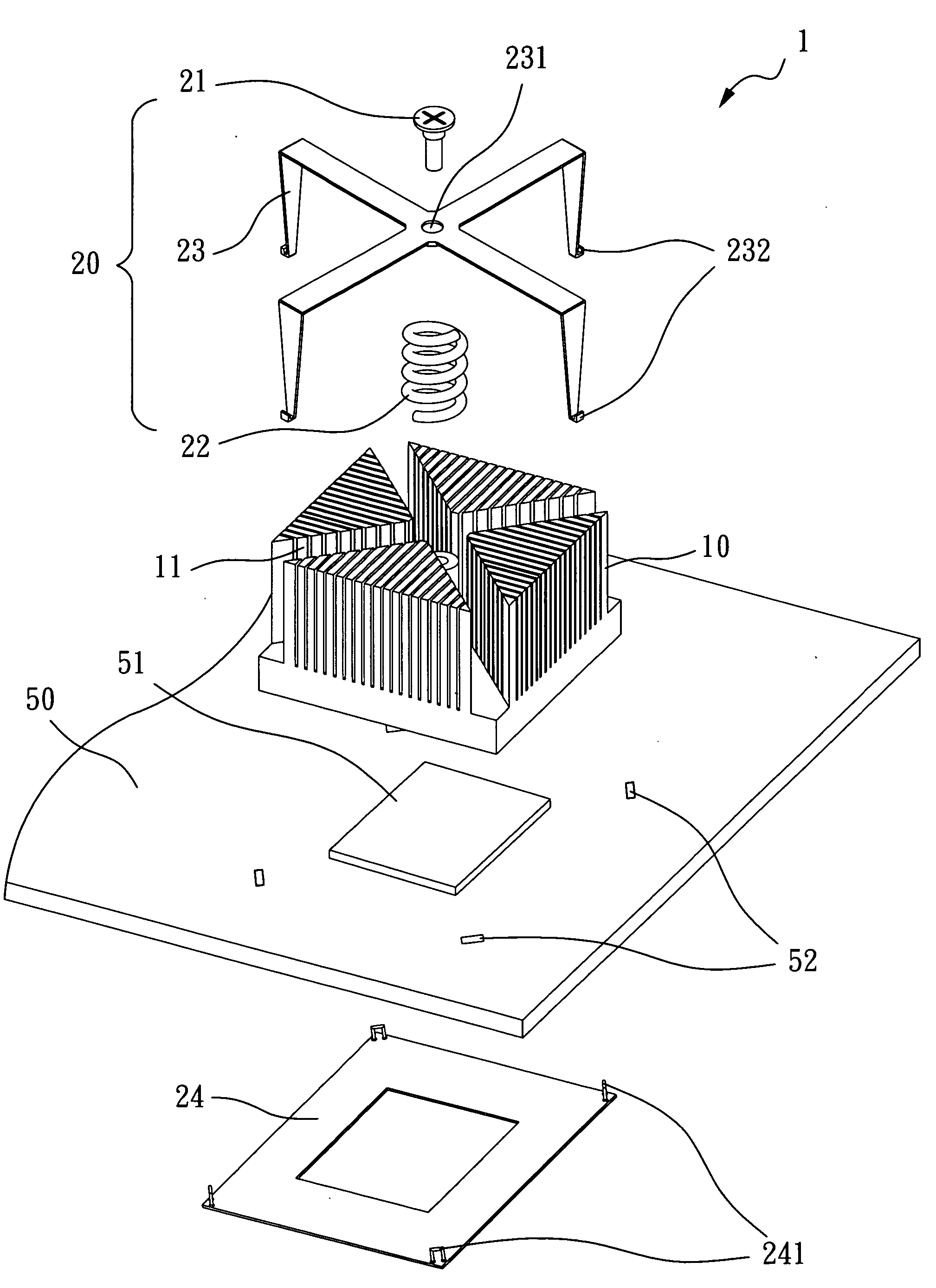
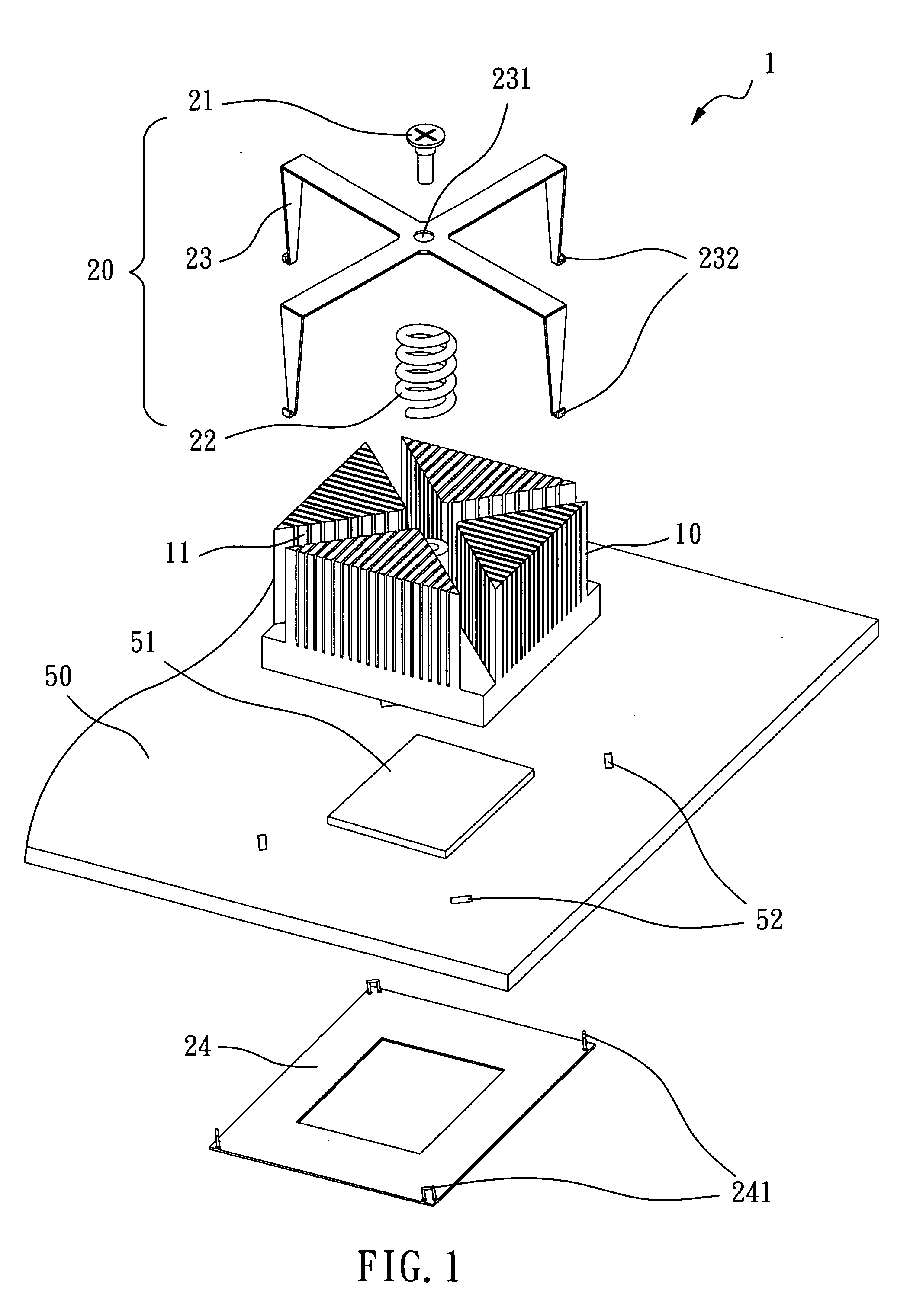
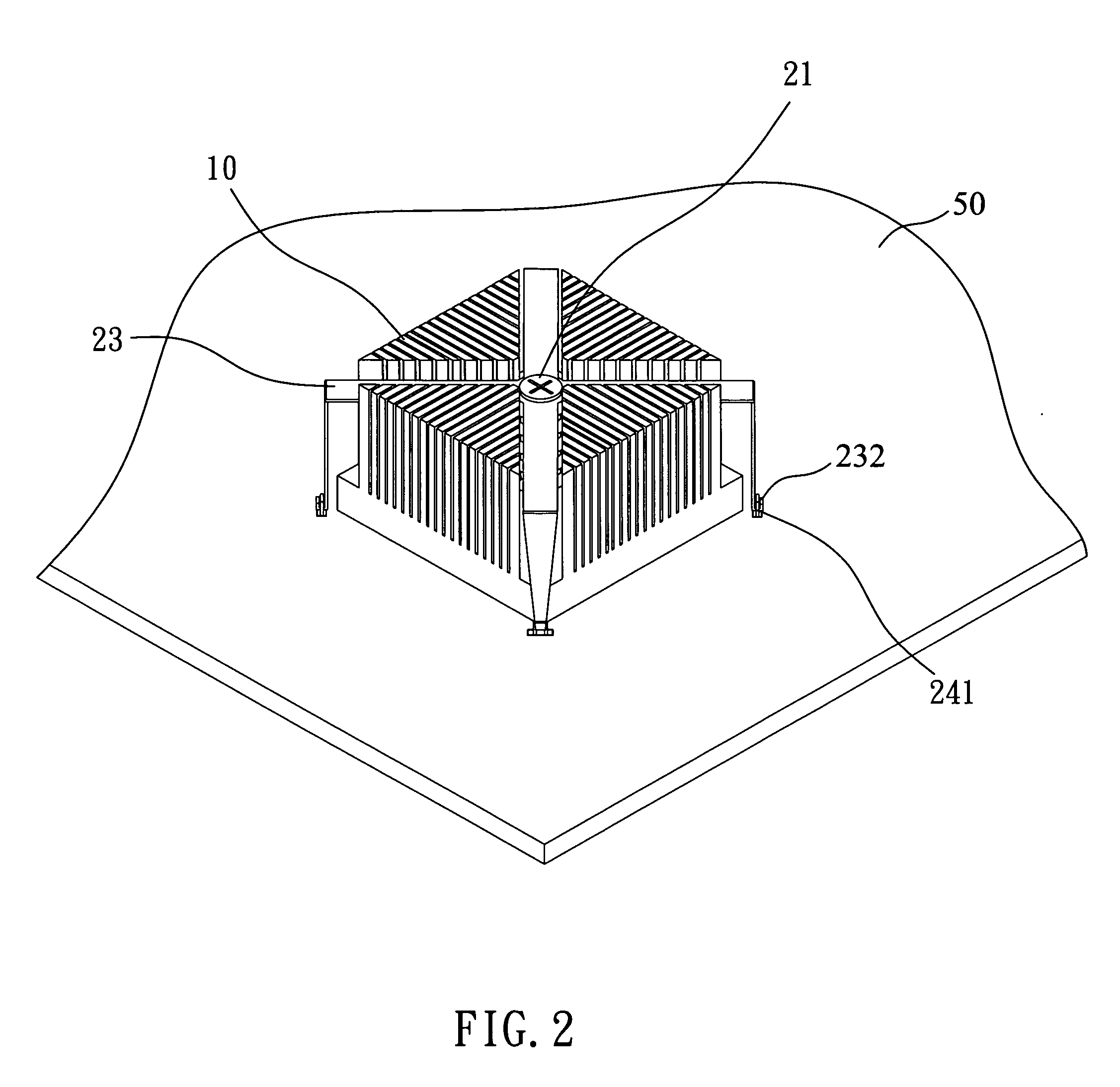
[0017]Refer to FIG. 1 for an explosive view of the heat sink of the present invention. As shown, the heat sink 1 of this invention may be mounted on an electronic apparatus (not shown) which comprises a circuit board 50 having an electronic component 51. The heat sink 1 of this invention comprises a fin structure 10 and a fastening assembly 20 which comprises an adjustable positioning member 21, an elastic member 22, and a hooking member 23. The elastic member 22 is disposed between the hooking member 23 and the fin structure 10 so that the adjustable positioning member 21 combines the hooking member 23, the elastic member 22, and the fin structure 10. The hooking member 23 may secure the heat sink 10 on the electronic component 51, and the adjustable positioning member 21 may be used to adjust the tightness between the heat sink 1 and the electronic component 51. In this embodiment, the adjustable positioning member 21 is a captive screw, which has the function of fastening and adj...


PUM


Abstract

A heat sink and an electronic apparatus using the same are disclosed. The heat sink comprises a fin structure and a fastening assembly; the fastening assembly comprises an adjustable positioning member, an elastic member, and a hooking member, the elastic member being disposed between the hooking member and the fin structure such that the adjustable positioning member combines the hooking member, the elastic member, and the fin structure; wherein the hooking member may secure the heat sink onto an electronic component, and the adjustable positioning member may be used to adjust the tightness between the heat sink and the electronic component.

Description

BACKGROUND OF THE INVENTION[0001]1. Field of the Invention[0002]The present invention relates to a heat sink; more particularly, this invention provides a heat sink which may be loosened or tightened to adjust its connection to an electronic component, and an electronic apparatus containing the heat sink. Via adjustment of that connection, the pressure on the electronic component may be evenly spread.[0003]2. Description of the Related Art[0004]With advances in technology, the processing speed and capabilities of an electronic component (e.g. the central processing unit of a computer) responsible for processing data have largely also increased. Meanwhile, a large amount of heat is generated during the operation of the electronic component. So far, several heat sinks have been developed to facilitate the heat dissipation of the electronic component. Most known heat sinks need a locking member to lock them onto the electronic component with or without a screw so as to secure the heat ...

Claims


Application Information

Patent Timeline
IPC IPC(8): H05K7/20
CPCH01L23/4093H01L23/467H01L2924/0002H01L2924/00
Inventor LEE, CHIA-MING
Owner WISTRON CORP
Why Eureka
Try Eureka