Method and apparatus for fuel cell packaging

Inactive Publication Date: 2005-01-04
ALLIEDSIGNAL INC +1
View PDF19 Cites 11 Cited by
  • Summary
  • Abstract
  • Description
  • Claims
  • Application Information

AI Technical Summary

Benefits of technology

The fuel cell receptacles also include manifolds and a plurality of conduits between the port interfacing surfaces and the manifolds. In a preferred embodiment, the manifolds vary in depth along the receptacles such that the conduits are substantially equal in length, thereby helping to equalize the pressure at the ports of each fuel cell.

Problems solved by technology

A problem with conventional fuel cell stacks is that the periphery of each fuel cell usually includes manifolds and seals which increase the size and therefore the cost of the fuel cells.
Another problem with conventional fuel cell packaging approaches is that they typically include molded rubber fluid interfaces to the fuel cells which are prone to leakage.
Another problem with conventional fuel cell packaging approaches is that it is often difficult to disassemble and reassemble the packaging to replace individual fuel cells, perform diagnostic tests, etc.

Method used


Image

  • Method and apparatus for fuel cell packaging
  • Method and apparatus for fuel cell packaging
  • Method and apparatus for fuel cell packaging

Examples


Embodiment Construction

The following is a detailed description of the best presently known mode of carrying out the invention. This description is not to be taken in a limiting sense, but is made merely for the purpose of illustrating the general principles of the invention.

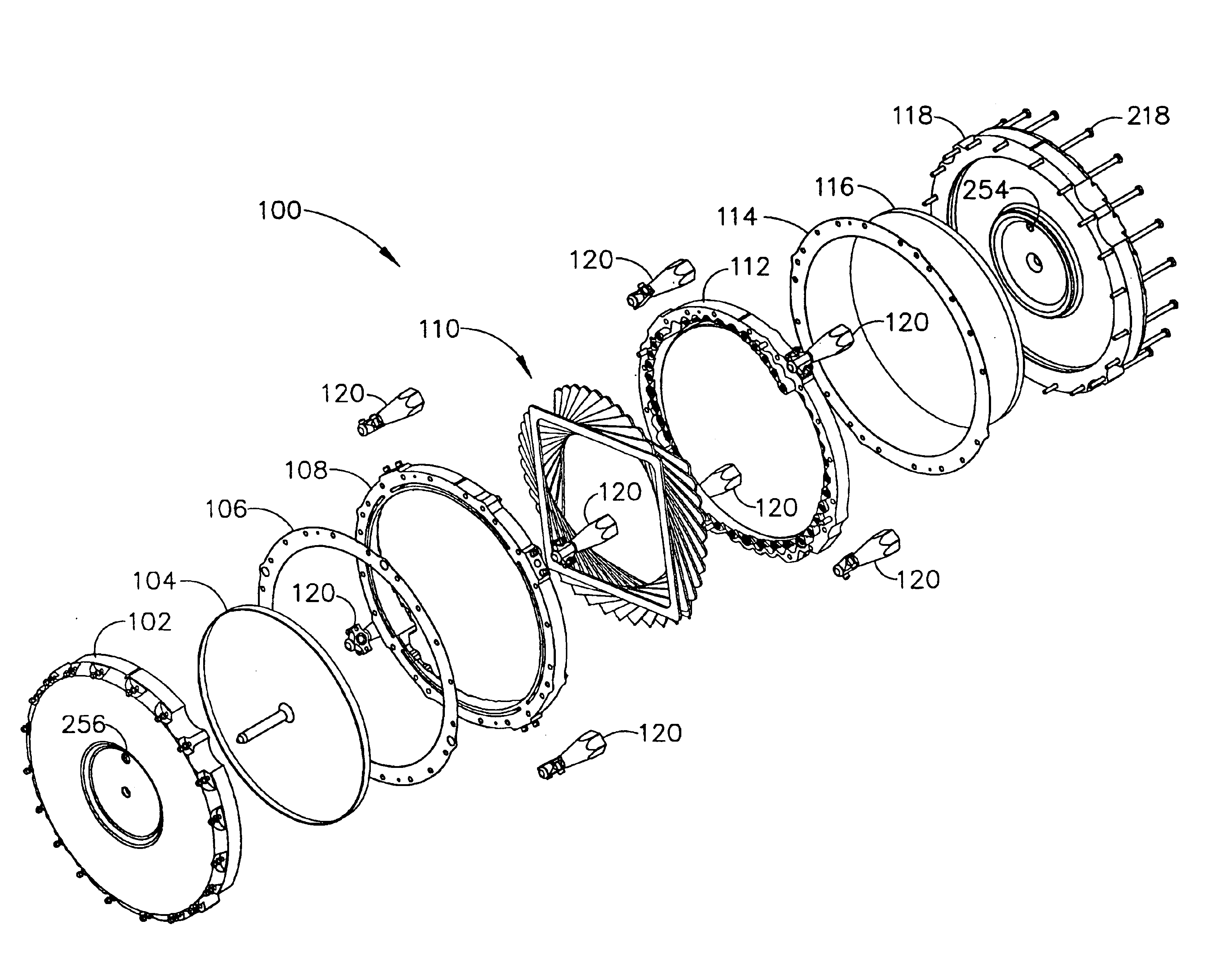
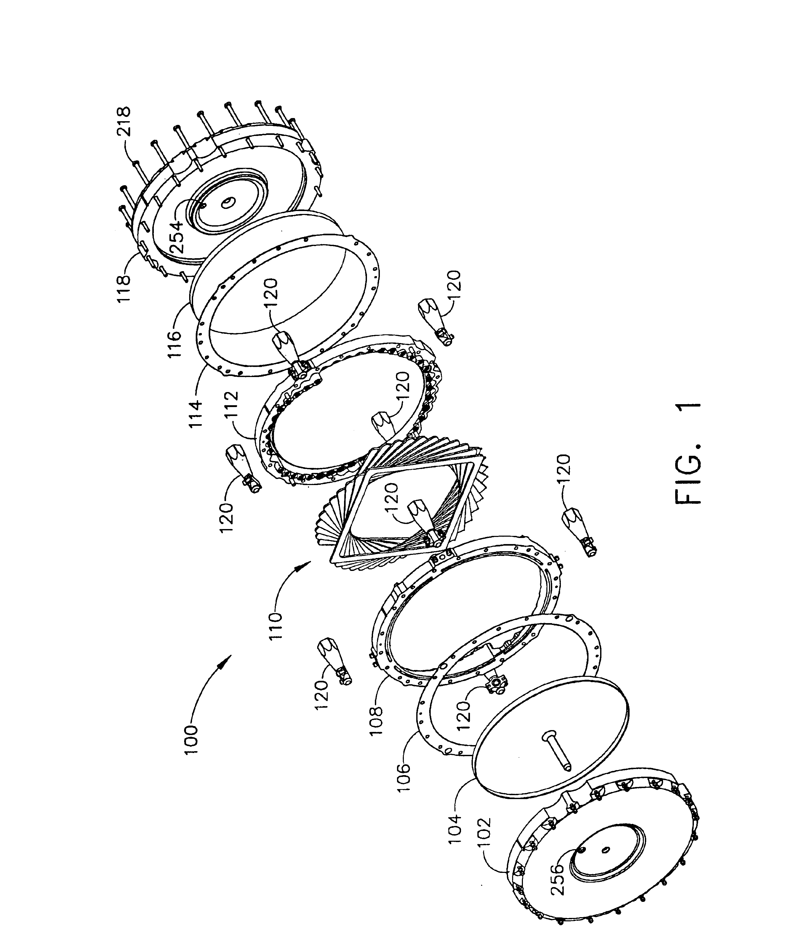
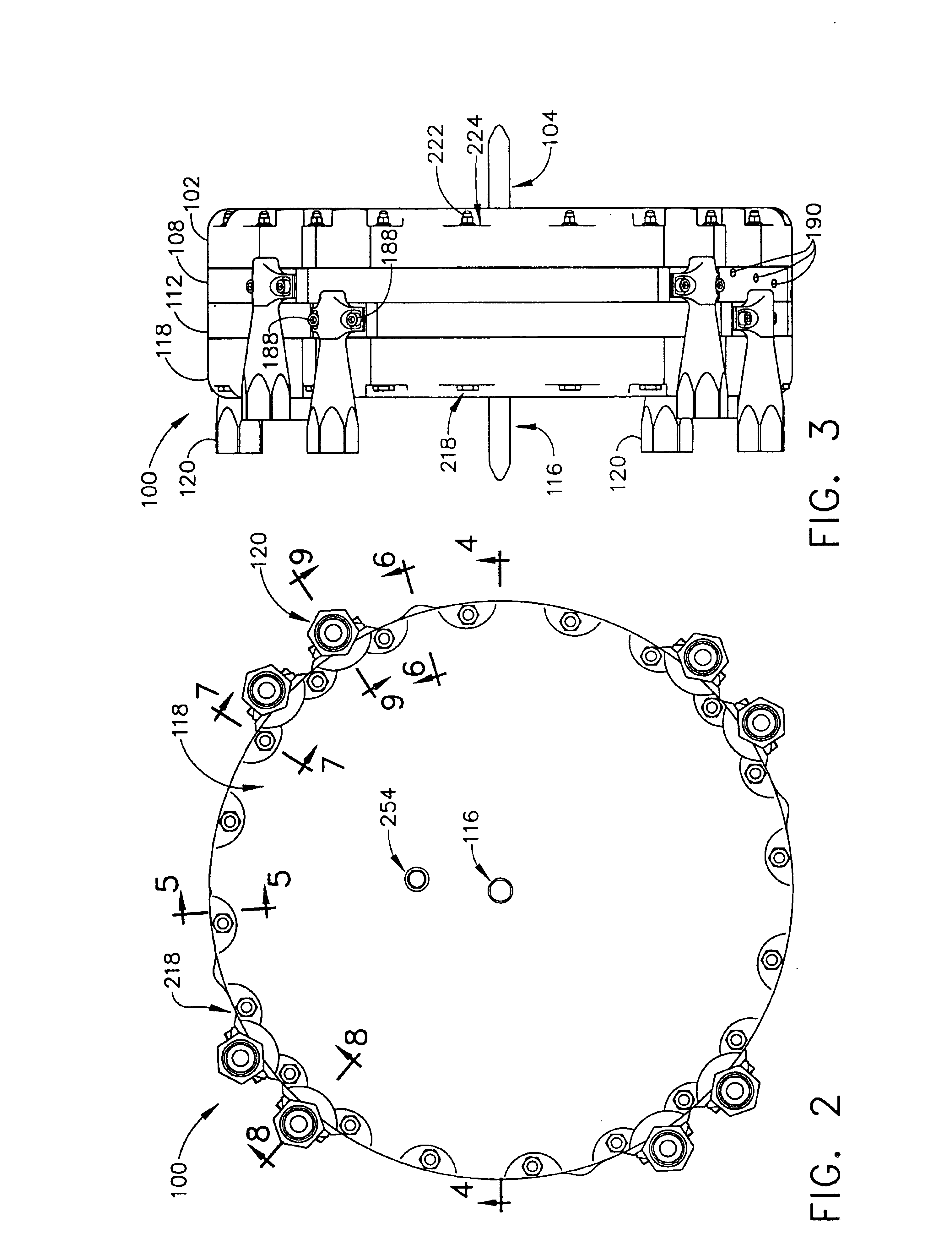
Referring to FIG. 1, an exemplary preferred fuel cell assembly 100 according to the present invention includes a bottom end cap 102, a bottom piston 104, a bottom shim 106, a bottom fuel cell receptacle 108, a fuel cell stack 110, a top fuel cell receptacle 112, a top shim 114, a top piston 116, a top end cap 118 and a plurality of manifold inlets / outlets 120. When the fuel cell assembly 100 is assembled as shown in FIGS. 2 and 3, the fuel cell stack 110 is entirely contained within a housing provided by the bottom receptacle 108 and the top receptacle 112.

As the receptacle 112 is complementary to the receptacle 108, the following discussion is applicable to both. Referring to FIGS. 12-14, an exemplary preferred receptacle 108 is shown...


PUM


Abstract

A method and apparatus for fuel cell packaging are embodied in a pair of complementary fuel cell receptacles within which a stack of fuel cells are housed in a staggered or spiral configuration. The fuel cells are provided with ports positioned in their corner portions. The fuel cell receptacles include a plurality of port interfacing surfaces over which the corners of the fuel cells are positioned, thereby providing direct fluidic interfaces between the flow field areas of the fuel cells and the receptacles. In a preferred embodiment, o-rings are employed at the fluidic interfaces between the fuel cells and the receptacles. The fuel cell receptacles also include manifolds and a plurality of conduits between the port interfacing surfaces and the manifolds. In a preferred embodiment, the manifolds vary in depth along the receptacles such that the conduits are substantially equal in length. The fuel cell receptacles are detachably secured together and facilitate the employment of a mechanism for pressing the stack of fuel cells together to ensure good electrical contacts between adjacent fuel cells of the stack.

Description

BACKGROUND OF THE INVENTION1. Field of InventionThe present invention relates generally to a method and apparatus for fuel cell packaging and, more specifically, to a method and apparatus for fuel cell packaging employing a receptacle shaped to receive fuel cells in a staggered or spiral configuration.2. Description of the Related ArtFuel cells such as, the Proton Exchange Membrane (“PEM”) fuel cell include a membrane electrode assembly (“MEA”). The MEA comprises a solid polymer electrolyte or ion exchange membrane positioned between an anode and a cathode which typically comprise finely divided carbon particles, very finely divided catalytic particles supported on the internal and external surfaces of the carbon particles, and proton conductive material intermingled with the catalytic and carbon particles.The catalytic particles, e.g., finely comminuted platinum, at each membrane / electrode interface induce the desired electrochemical reaction. On the anode side, the fuel (e.g., hyd...

Claims


Application Information

Patent Timeline
IPC IPC(8): H01M2/00H01M2/02H01M8/04H01M8/00H01M8/10H01M8/02H01M8/24
CPCH01M8/0271H01M8/241H01M8/2465Y02E60/50H01M8/248H01M8/2415H01M8/2485H01M8/2404H01M8/2484
Inventor BRUDNICKI, MYRON J.
Owner ALLIEDSIGNAL INC
Why Eureka
Try Eureka