Device for the steam treatment of a moving fiber strand

a technology of moving fiber and steam treatment, which is applied in the direction of cleaning using liquids, other washing machines, textiles and papermaking, etc., can solve the problems of hardly being able to carry out precise conditioning of fiber strands, unable to move sealing rollers, and requiring considerable sealing efforts, so as to achieve constant possible sealing conditions, improve the efficiency of nip sealing, and avoid the effect of slipping

Inactive Publication Date: 2007-10-11
SAURER GMBH & CO KG
View PDF12 Cites 4 Cited by
  • Summary
  • Abstract
  • Description
  • Claims
  • Application Information

AI Technical Summary

Benefits of technology

[0009] A special advantage of the invention is that a contact seal combined with a nip seal is used for sealing the chamber assigned to the sealing rollers from the roller circumference. For this purpose, the chamber comprises a displaceable sealing strip opposite the roller circumference of the displaceable sealing roller, which sealing strip is pre-stressed against the circumference of the sealing roller. For this purpose, the sealing strip is held within a sealing surface of the chamber, which sealing surface seals the nip opposite the roller circumference of the sealing roller. The contact seal formed between the chamber and the roller circumference is thus embedded within a nip seal and is shielded from the actual chamber. Furthermore, it is possible to guide the sealing strip irrespective of the rotational direction of the sealing rollers. The pre-stress acting on the sealing strip further enables relative movements of the sealing roller towards the chamber without any gap formation. The invention is thus particularly suitable for implementing the smallest treatment chambers irrespective of the roller geometry.
[0010] The refinement of the invention in which the sealing surface is designed on a top plate, which extends parallel to the sealing roller and in which the sealing strip is held in a guide groove of the top plate, which guide groove is connected by means of a pressure channel in the groove bottom to the interior of the chamber, is characterized in that the pre-stress of the sealing strip for its abutment against the circumferential surface of the sealing roller is determined by the internal pressure prevailing in the chamber. It is thus possible to adjust an advantageous leakproofness of the sealing roller, thus enabling a steam treatment at operating pressures exceeding 20 bar.
[0011] In order to ensure at the start of the process or even at lower operating pressures that the sealing strip abuts against the roller circumference of the sealing roller with contact thereto, at least one pressure spring is stressed between the sealing strip and the groove bottom of the guide groove, by means of which pressure spring the sealing strip is held with a minimum contact pressure against the surface of the sealing roller.
[0012] In order to achieve high efficiency of the nip seal in addition to the contact seal, the sealing surface for sealing the nip is designed with a shape, which is adapted firstly to the circumference of the sealing roller and secondly to an operationally permissible change in the position of the sealing roller according to a particularly advantageous refinement of the invention. It is thus possible to achieve pressure decay within the nip seal in any operating position of the displaceable roller. Furthermore, it is advantageously possible to ensure that the gap existing within the contact seal, between the sealing surface and the roller circumference remains substantially constant regardless of the respective operating position of the sealing rollers.
[0013] In order to achieve the most constant possible sealing conditions on the sealing rollers for sealing the feed chamber or the exit chamber, the seals between the chamber and the fixed sealing rollers are designed identically. Particularly, the contact pressure adjusted depending on the chamber pressure between the sealing strip and the circumference of the sealing roller has a wear-resistant effect since the sealing strips are constantly held against the sealing roller with the required contact pressure, which is adapted to the operating conditions in each case.
[0014] The refinement of the invention in which the sealing rollers comprise a steel jacket and in which the sealing strips consist of a metallic alloy, is particularly suitable for enabling a high-temperature treatment of the fiber strand. It is thus possible to set a steam atmosphere of up to 225° in the steam chamber.

Problems solved by technology

In principle, however, the shortcoming of devices of this type is that the displaceable sealing roller, which is held in a changed position, requires considerable sealing effort in order to prevent the steam from leaking on the circumferential surfaces of the sealing roller.
In addition to the high requirement of steam for the steam treatment, it is further hardly possible to carry out a precise conditioning of the fiber strand in the oversized steam chamber.
Extreme signs of wear are thus unavoidable on the sealing strips.
However, these devices known from the prior art comprise two fixed sealing rollers with the result that it is not possible to adjust the nip.
Consequently, a change in the position of any of the sealing rollers would necessarily lead to leakages.

Method used


Image

  • Device for the steam treatment of a moving fiber strand
  • Device for the steam treatment of a moving fiber strand
  • Device for the steam treatment of a moving fiber strand

Examples


Embodiment Construction

[0027] The present invention now will be described more fully hereinafter with reference to the accompanying drawings, in which some, but not all embodiments of the invention are shown. Indeed, the present invention may be embodied in many different forms and should not be construed as limited to the embodiments set forth herein; rather, these embodiments are provided so that this disclosure will satisfy applicable legal requirements. Like numbers refer to like elements throughout.

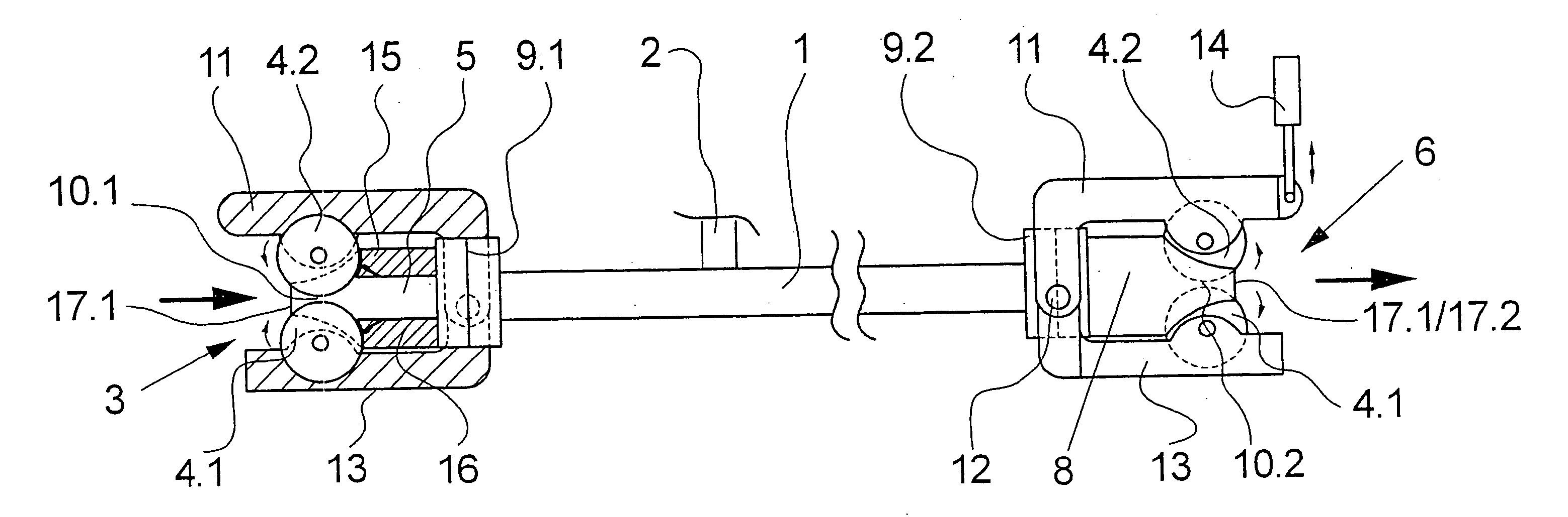
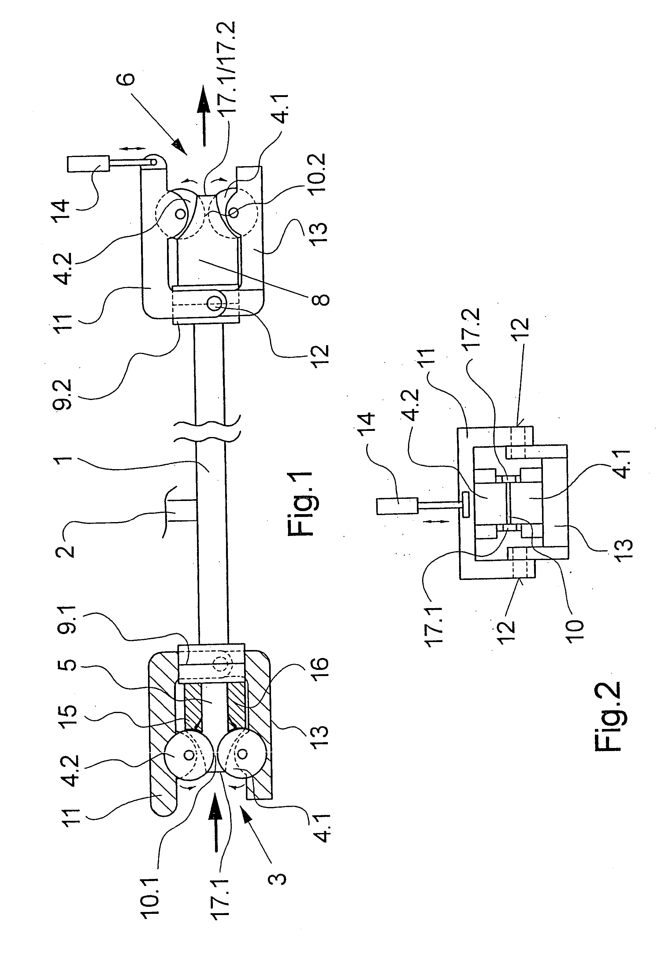
[0028]FIGS. 1 and 2 show different views of a first exemplary embodiment of the device according to the invention. FIG. 1 schematically shows a lateral view of the exemplary embodiment while FIG. 2 shows a front view thereof. The following description refers to both the figures unless express reference is made to any one of the figures.

[0029] The exemplary embodiment comprises an elongated steam chamber 1, which is substantially provided with a cylindrically hollow shape. The steam chamber 1 is connected...


PUM


Abstract

The invention relates to a device for the steam treatment of a moving fiber strand, comprising an elongated steam chamber. To seal the steam chamber, a pair of feed rollers is connected to and seals a feed chamber on a feed side in such a way that the nip constitutes the feed into the steam chamber. The opposing exit side is equipped with a pair of exit rollers, which forms a second nip and which is connected to and seals the other end of the steam chamber by means of an exit chamber, in such a way that the second nip constitutes the exit from the steam chamber. The feed roller pair and the exit roller pair are respectively formed by a fixed sealing roller and a displaceable sealing roller. The aim of the invention is to achieve a seal between the sealing roller and the associated sealing chamber, irrespective of the operating position of the displaceable roller. To achieve this, the feed chamber and/or exit chamber comprise(s) a sealing surface lying opposite the roller circumference of the displaceable sealing roller, thus sealing the nip, and a displaceable sealing strip, which is located in said sealing surface and is pre-stressed against the circumference of the sealing roller.

Description

CROSS REFERENCE TO RELATED APPLICATION [0001] The present application is a continuation of international application PCT / EP2005 / 011079, filed 14 Oct. 2005, and which designates the U.S. The disclosure of the referenced application is incorporated herein by reference.BACKGROUND OF THE INVENTION [0002] The invention relates to a device for the steam treatment of a moving fiber strand. A device of this type has been disclosed in the U.S. Pat. No. 4,949,558. For the purpose of steam treatment of a moving fiber strand, the device known from the prior art comprises an elongated steam chamber, which comprises a feed roller pair at a feed end and an exit roller pair at an exit end for sealing the steam chamber. The feed roller pair is connected to the steam chamber in a pressure-tight manner by means of a feed chamber and the exit roller pair is likewise connected to the steam chamber in a pressure-tight manner by means of an exit chamber. The feed roller pair and the exit roller pair each ...

Claims


Application Information

Patent Timeline
Patent Type & Authority Applications(United States)
IPC IPC(8): B08B3/12
CPCD06B23/18
Inventor SCHOENNAGEL, BERNHARDSCHWARZ, OLAFSCHUTT, GUNTERMUNSTER, UWE
Owner SAURER GMBH & CO KG
Why Eureka
Try Eureka