Condylus screw

a technology of condylus and screw, which is applied in the field of osteosynthetic condylus screw, can solve the problems of tensile load and widening, and achieve the effect of optimal adaptation to the bon

Inactive Publication Date: 2005-07-19
STRYKER EURO OPERATIONS HLDG LLC
View PDF39 Cites 31 Cited by
  • Summary
  • Abstract
  • Description
  • Claims
  • Application Information

AI Technical Summary

Benefits of technology

[0004]It is the object of the invention to provide an osteosynthetic device whi...

Problems solved by technology

However, there is possibly a danger he...

Method used


Image

  • Condylus screw
  • Condylus screw
  • Condylus screw

Examples


Embodiment Construction

[0022]Initially, it should be noted that the drawings are not to scale.

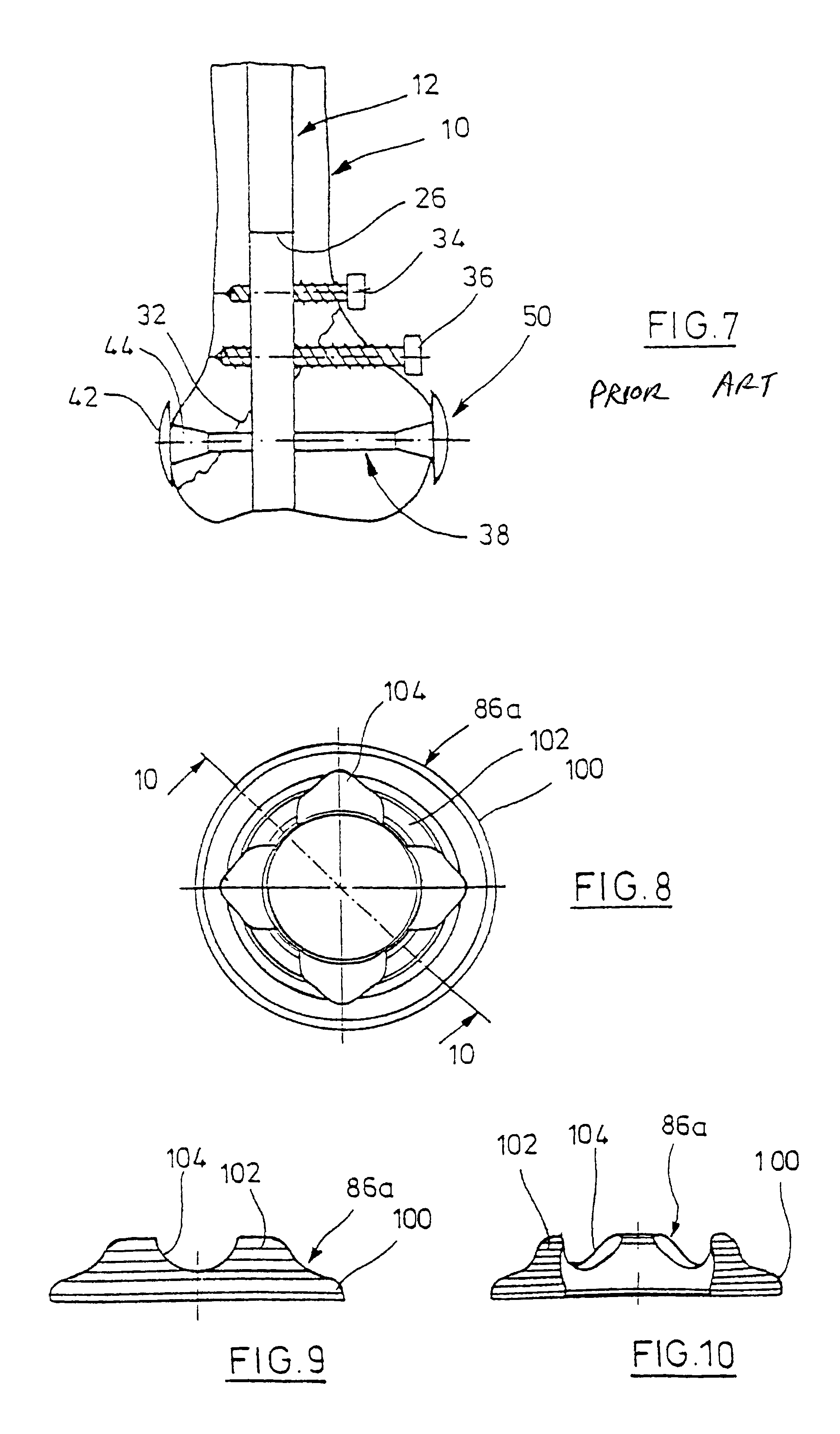
[0023]Referring to FIG. 7, the distal region of a femur 10 is shown which receives a bone nail 12. It is inserted through a bore which is subcondularly made in a retrograde way. This is explained in detail in U.S. Pat. No. 6,010,505 the teachings of which are incorporated herein by reference.

[0024]The distal region of bone nail 12 is provided with three transverse bores. FIG. 7, the state of the art, further makes it evident that the condylus region of the femur is damaged by an obliquely extending fracture having a fracture line 32. Two bone screws 34, 36 are passed through two of the three transversal bores and serve to anchor nail 12 in femur 10. A condylus screw 38, which is composed of a shank part 50 and a female-type part 42, is passed through the distal transverse bore. The two parts 42, 50 are screwed onto each other (with the thread not being shown). The female-type part 42 and the shank part 50 have fl...


PUM


Abstract

An osteosynthetic device, particularly a condylus screw, which is composed of a female-type part and a shank part which each have a flanged portion. At least one flanged portions is a separate part and is formed as a ring-shaped bearing component which forms a bearing seat for a spherically-shaped end portion of the female-type part and/or the shank part and wherein the bearing is movably supported on the female-type and/or the shank part.

Description

BACKGROUND OF THE INVENTION[0001]The invention relates to an osteosynthetic condylus screw generally for use with a bone nail. In certain types of fractures the condylus screw can be used without the bone nail.[0002]A supracondylar or retrograde bone nail is disclosed in U.S. Pat. No. 6,010,505. It has an elongate shank which is shaped relatively short as compared to other femoral nails and is driven in through a bore which distally opens out between the condyli and, for the rest, follows the bone channel. To take good care of a fracture in the condylus region, a so-called condylus screw is provided which can be passed through a transverse bore of the bone nail. The condylus screw has a female-type portion and a shank portion which are screwed together. At each end, the portions have a flange-like extension which bears on the bone side which faces it. Such a screw makes it easy to efficiently compress the bone fragments and retain them on the nail. The latter normally is designed as...

Claims


Application Information

Patent Timeline
IPC IPC(8): A61B17/68A61B17/72A61B17/86A61B17/58
CPCA61B17/683A61B17/725A61B17/72A61B17/8695
Inventor SEEMANN, MICHAEL
Owner STRYKER EURO OPERATIONS HLDG LLC
Why Eureka
Try Eureka