Milling insert and a milling tool

a technology of milling insert and milling tool, which is applied in the direction of milling equipment, turning apparatus, transportation and packaging, etc., can solve the problems of unstable localization and relative cost of us

Active Publication Date: 2007-03-29
SECO TOOLS AB
View PDF7 Cites 119 Cited by
  • Summary
  • Abstract
  • Description
  • Claims
  • Application Information

AI Technical Summary

Benefits of technology

[0004] It is desirable to provide a milling insert for milling, whic

Problems solved by technology

Drawbacks of known milling inserts are that they are relat

Method used


Image

  • Milling insert and a milling tool
  • Milling insert and a milling tool
  • Milling insert and a milling tool

Examples


Embodiment Construction

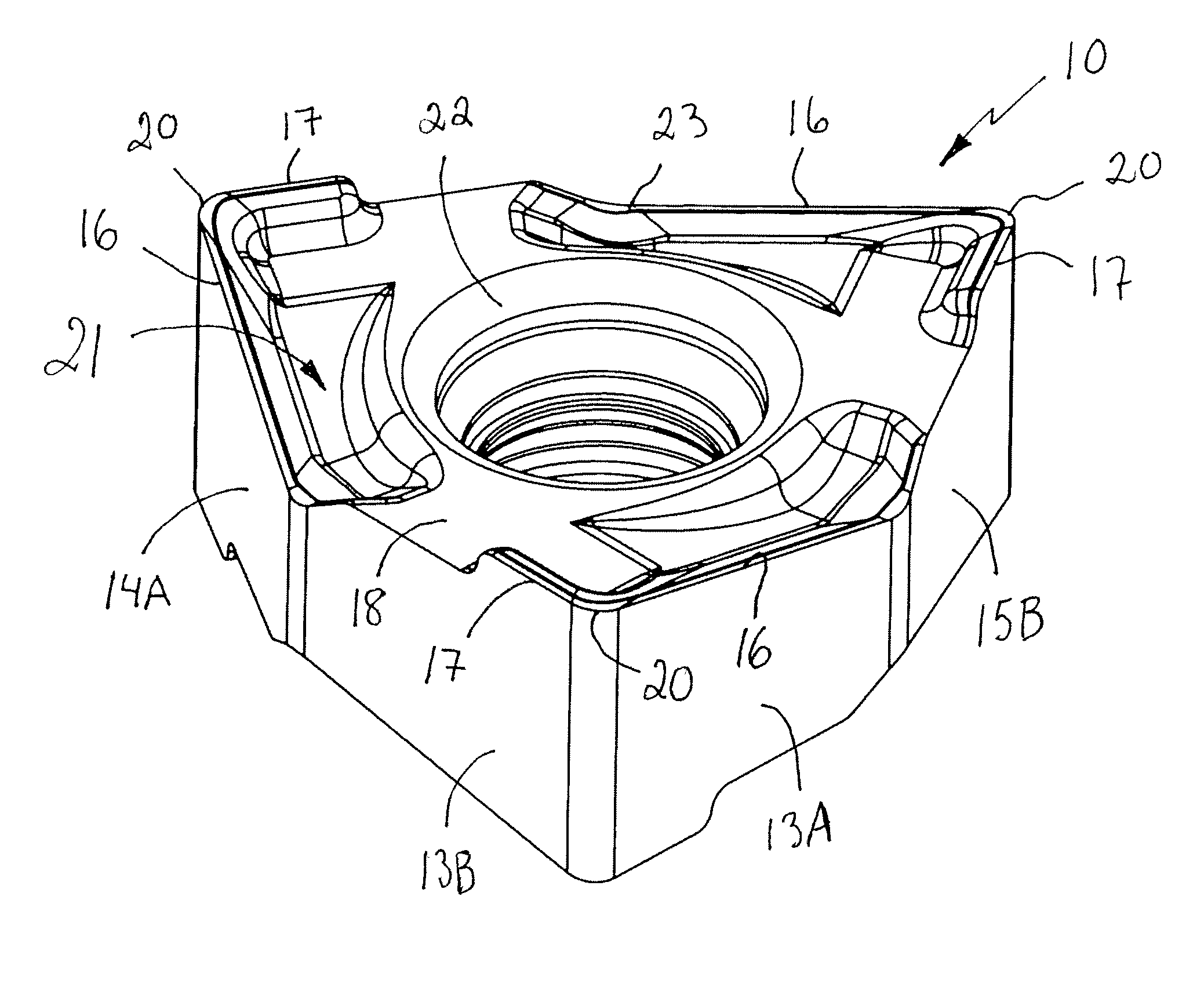
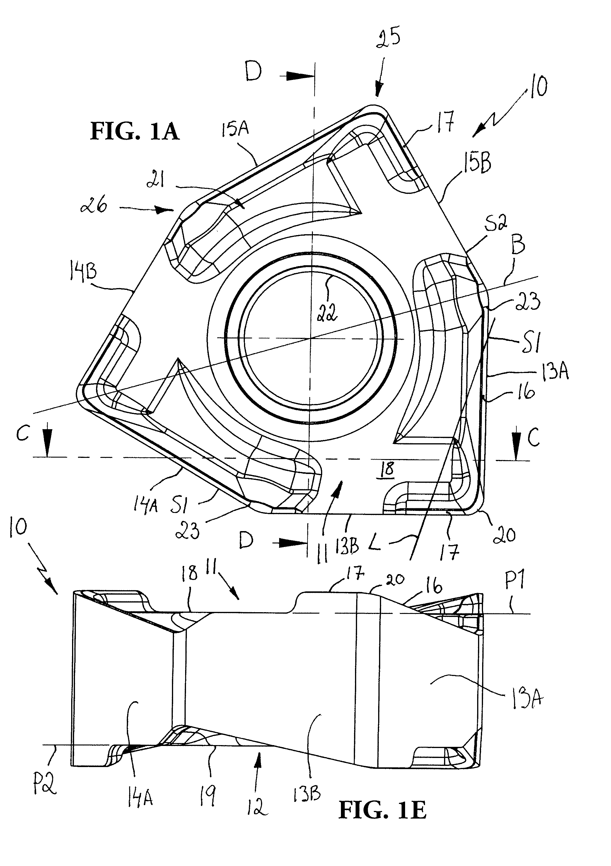
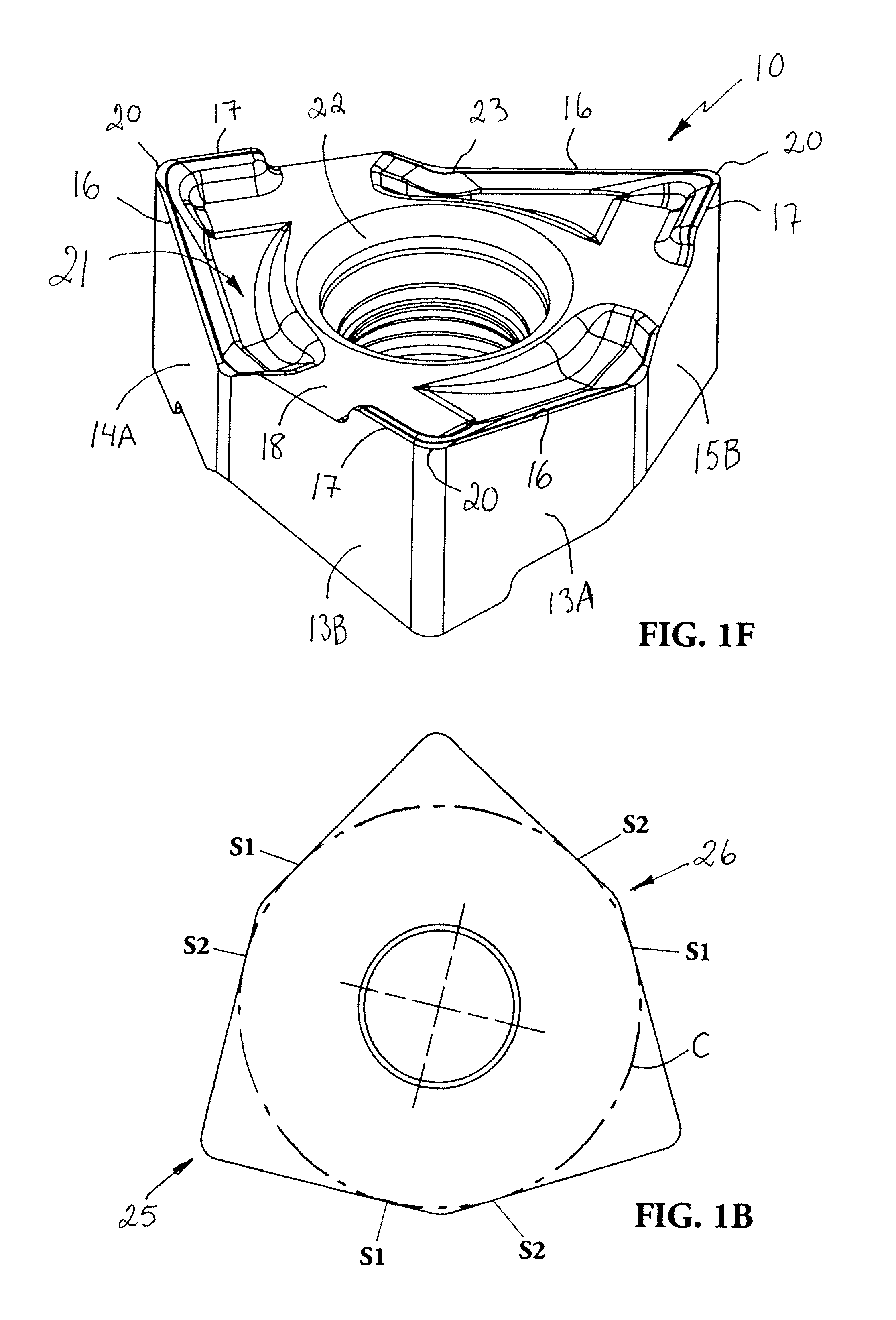
[0016]FIGS. 1A-1F show a double sided or indexable cutting insert 10 for milling, hereinafter called milling insert, according to the present invention. The milling insert 10 has a trigon-shaped or hexagonal basic shape and is made of directly pressed hard metal. Alternatively, the milling insert can have four or five corners. With “hard metal” is here meant WC, TiC, TaC, NbC, etc., in sintered combination with a binder metal such as for example Co or Ni. The milling insert is preferably at least partly coated with layer of for example Al2O3, TiN and / or TiCN. In certain cases there can be well-founded that the cutting edges are made of brazed on super hard materials such as CBN or PCD. In FIG. 1B the basic shape of the milling insert is shown where 25 depicts right angled cutting corners provided with edges, whereof one corner is active at the time, and where 26 depicts blunt passive corners. The blunt corners 26 do normally not cut during milling. The milling insert is intended to ...


PUM

PropertyMeasurementUnit
Angleaaaaaaaaaa
Angleaaaaaaaaaa

Abstract

The present invention relates to an indexable milling insert and a milling tool for chip removing machining. The milling insert is intended to be able to mill substantially perpendicular corners in a work piece. The milling insert comprises an upper side, a lower side and edge surfaces extending therebetween. The upper side and the lower side are substantially identical. An imaginary circle inscribed in the milling insert touches the milling insert periphery in four to six points. Lines of intersection between the edge surfaces and the sides form relative to each other substantially perpendicular main cutting edges and minor cutting edges. Each of the sides includes a support surface, each of which being provided in a plane. Each minor cutting edge projects from the plane of the associated support surface. Each major cutting edge intersects the plane of the associated support surface.

Description

BACKGROUND AND SUMMARY [0001] The present invention relates to a milling insert and a milling tool for chip removing machining. [0002] Milling inserts for milling of 90° corners in metallic workpieces are previously known, see for example U.S. Pat. No. 6,142,716. Drawbacks of known milling inserts are that they are relatively expensive to use and provides unstable localization. [0003] It is desirable to provide an economically advantageous milling insert for milling of 90° corners in metallic workpieces. [0004] It is desirable to provide a milling insert for milling, which enables rigid localization of the milling insert in a milling body. [0005] According to an aspect of the present invention an indexable milling insert is provided for milling substantially perpendicular corners in a work piece, the milling insert including an upper side, a lower side, and edge surfaces extending between the upper and lower sides, the upper and lower sides being substantially identical, wherein an ...

Claims


Application Information

Patent Timeline
IPC IPC(8): B23C5/00
CPCB23B27/16Y10T407/24B23C5/202B23C2200/0405B23C2200/0444B23C2200/205B23C2200/286B23C2200/326B23C2222/28B23C2228/10Y10T407/1908Y10T407/245Y10T407/23Y10T407/235B23C5/06B23C5/20B23B27/1611B23C5/205B23C2200/203
Inventor KOSKINEN, JORMA
Owner SECO TOOLS AB
Why Eureka
Try Eureka