Male terminal fitting and blank therefor

a terminal fitting and blank technology, applied in the direction of dolls, contact member manufacturing, coupling device connections, etc., to achieve the effect of reducing rigidity

Active Publication Date: 2007-03-29
SUMITOMO WIRING SYST LTD
View PDF9 Cites 3 Cited by
  • Summary
  • Abstract
  • Description
  • Claims
  • Application Information

AI Technical Summary

Benefits of technology

[0008] The invention relates to a male terminal fitting with opposite front and rear ends. A contact is disposed at the front end and is configured for contact with a female terminal fitting. A tube is behind the contact and is wider than the contact. A link is provided between the tube and the contact and gradually widens from the contact toward the tube. The link includes a base wall, first and second side walls that extend from the base wall and a ceiling that extends from one of the first side wall. The base wall, the side walls and the ceiling are substantially continuous with the contact and the tube. However, the ceiling of the link does not extend the full width of the tube, and an unconnected edge extends across part of the front of the tube. Accordingly, bending rigidity is lower as compared to a case where the ceiling and the tube are connected over the entire width of the tube. Thus, the contact and of the link are more deflectable in response to external forces on the contact.

Problems solved by technology

However, the ceiling of the link does not extend the full width of the tube, and an unconnected edge extends across part of the front of the tube.

Method used


Image

  • Male terminal fitting and blank therefor
  • Male terminal fitting and blank therefor
  • Male terminal fitting and blank therefor

Examples


first embodiment

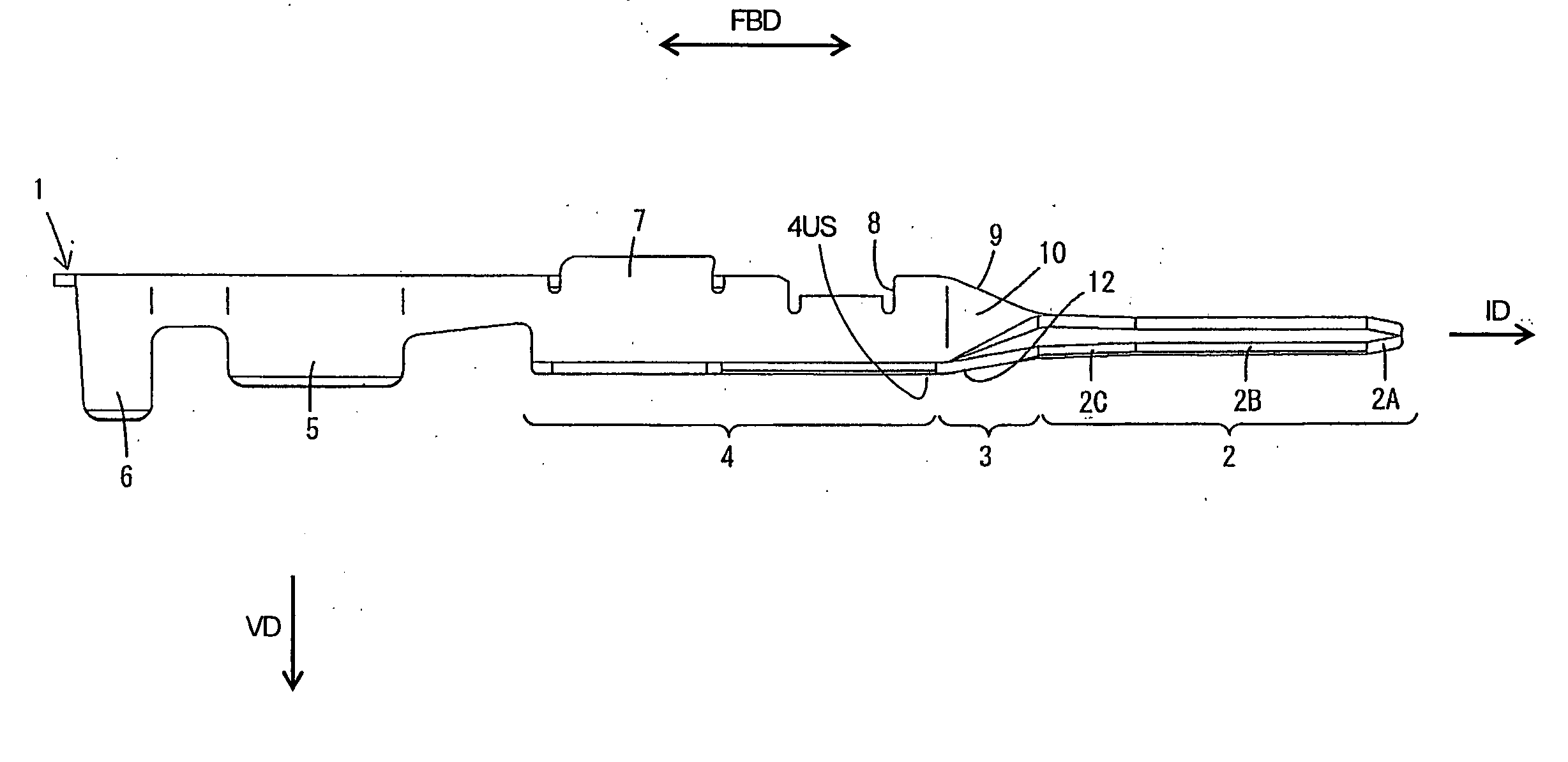
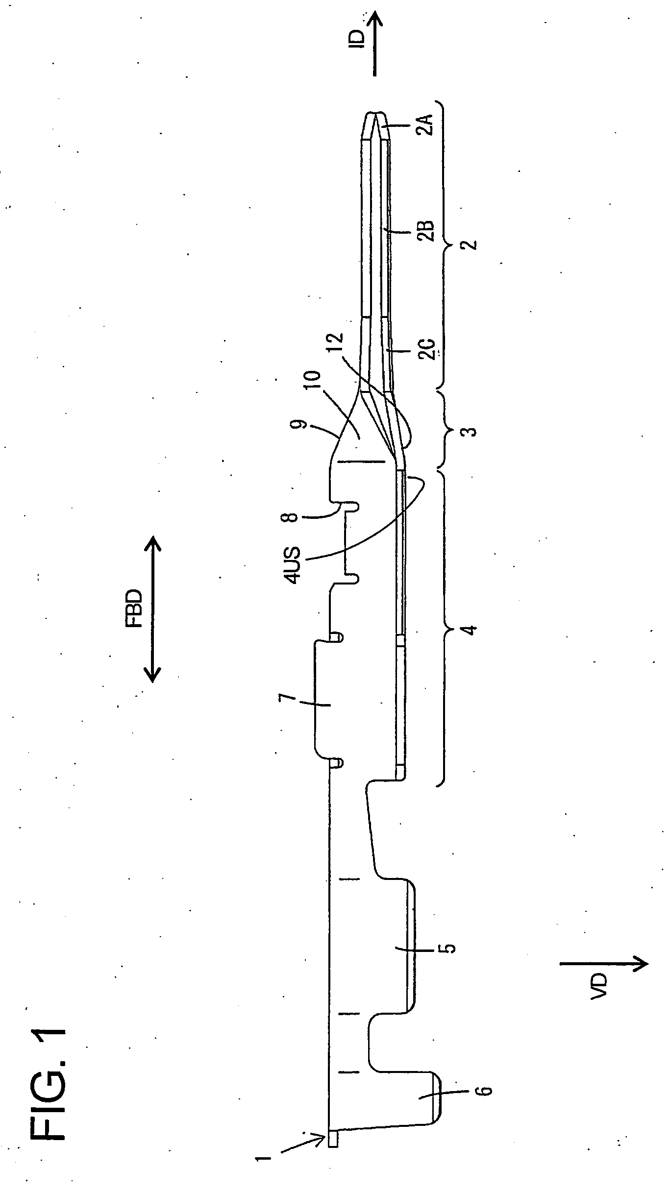
[0027] The male terminal fitting 1 of the first embodiment is formed by bending a substantially flat conductive metal plate 1PM of a specified shape. The male terminal fitting 1 has an insulation barrel 6 that can be crimped, bent or folded into connection with an insulation coating of a wire W and a wire barrel 5 that can be crimped, bent or folded into connection with a conductive core exposed from the insulation coating. A substantially rectangular tube 4 is formed in an intermediate position of the male terminal fitting 1, and a contact 2 projects forward of the rectangular tube 4 via a link 3. Thus, the male terminal fitting 1 is substantially long along forward and backward directions FBD, and can be accommodated into a cavity of a connector housing (not shown).

[0028] As shown in FIG. 1, an engaging portion 8 is formed at a front portion of the rectangular tube 4 and is engageable with a lock (not shown) provided in the cavity. Front and rear grooves are formed in an outer sur...

second embodiment

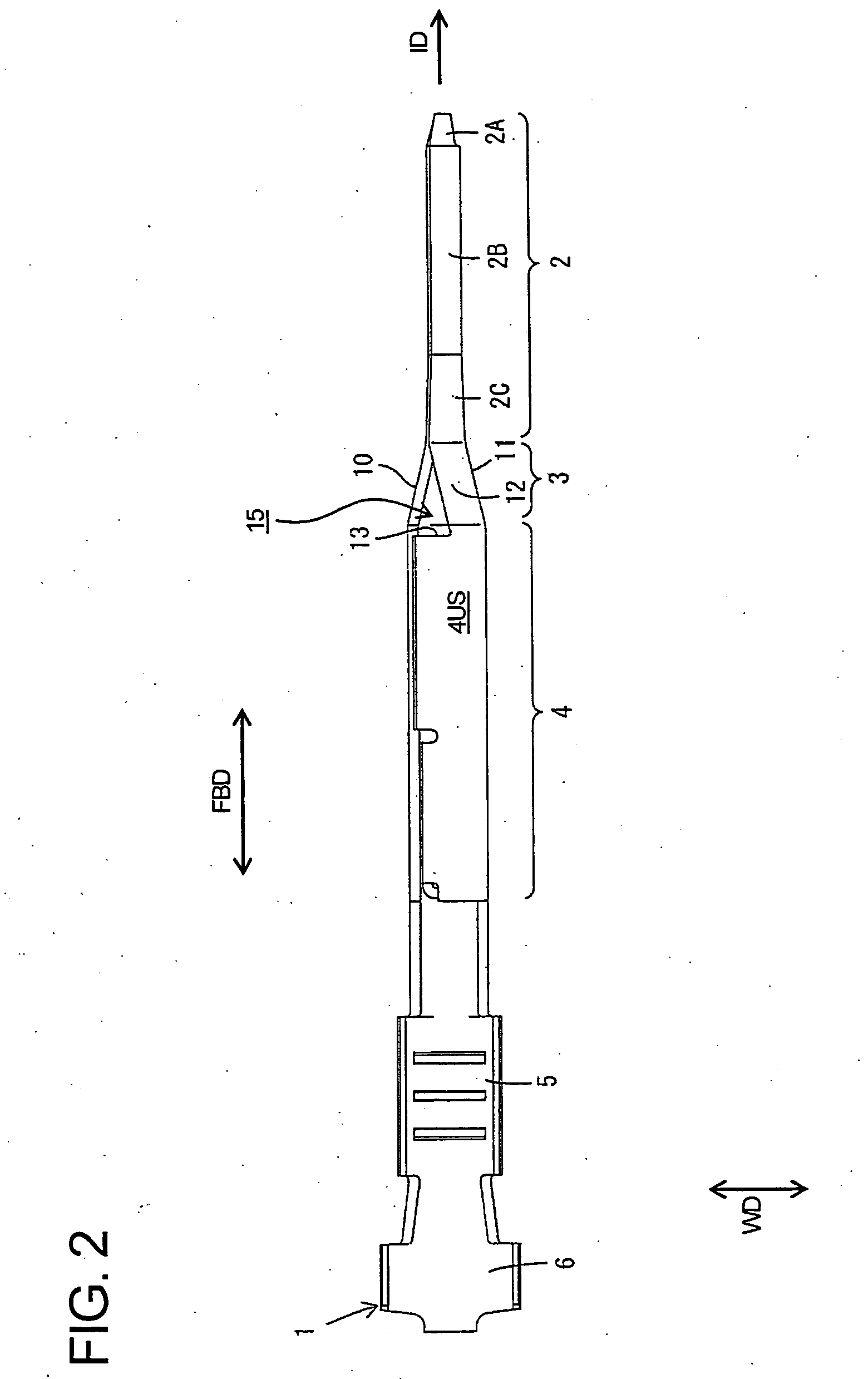
[0032] the invention is described with reference to FIGS. 5 to 8. In the second embodiment, a closing plate 14 closes the opening 15 formed in the link 3 of the first embodiment is closed. The other construction is the same as or similar to the first embodiment. These similar parts are identified by the same reference numerals in FIGS. 5 to 8, but are not described again.

[0033] The closing plate 14 has a shape that substantially conforms to the shape of the opening 15 and is substantially continuous with the upper edge of the second side wall of the link 3 that is not connected with the ceiling wall 12. It should be noted that the second embodiment is the same as the first embodiment in that the front edge of the upper wall 4US of the rectangular tube 4 has the unconnected edge irrespective of whether the front edge is coupled to the closing plate 14.

[0034] As described above, the closing plate 14 of the second preferred embodiment, prevents external matter or the like from intrudi...


PUM


Abstract

A male terminal fitting (1) is formed by bending a flat metal plate worked into a specified shape and includes a contact (2), a rectangular tube (4) formed to be wider than the contact (2), and a link (3) between the contact (2) and the rectangular tube (4). The link (3) is not connected with the front edge of the upper surface of the rectangular tube (4) over the entire width. Thus, bending resistance against an external force can be improved by increasing deflectability while holding down bending rigidity.

Description

[0001] This application is a divisional of U.S. patent application Ser. No. 11 / 344,649, filed on Feb. 1, 2006.BACKGROUND OF THE INVENTION [0002] 1. Field of the Invention [0003] The invention relates to a male terminal fitting and a blank therefor. [0004] 2. Description of the Related Art [0005] U.S. Pat. No. 5,649,842 and FIG. 9 herein disclose a male terminal fitting. With reference to FIG. 9, the male terminal fitting is identified generally the numeral 100 and has a terminal contact portion 101 for connection with a female terminal fitting. A link 102 is rearward of the terminal contact portion 101 and a rectangular tube 103 extends rearward from the link 102. A barrel 104 is at the rear end of the male terminal fitting 100 and is configured for connection with a wire W (not shown). [0006] An external force can act on the terminal contact portion 101 and can concentrate stress on a boundary between the link 102 and the terminal contact portion 102, thereby causing a bend beyond ...

Claims


Application Information

Patent Timeline
Patent Type & Authority Applications(United States)
IPC IPC(8): H01R4/18
CPCH01R13/04H01R43/16H01R13/055H01R13/05A63H3/14A63H3/46A63J19/006
Inventor NAKAMURA, KEIICHIISHIKAWA, RYOTARONORO, YUTAKAKOBAYASHI, YUTAKAKAWASE, HAJIME
Owner SUMITOMO WIRING SYST LTD
Why Eureka
Try Eureka