Posterior dynamic stabilization systems and methods

a dynamic stabilization and anterior stabilization technology, applied in the field of anterior dynamic stabilization systems and methods, can solve the problems of further damage, limited use of capping techniques, and disadvantages of caps

Active Publication Date: 2007-03-29
DEPUY SPINE INC (US)
View PDF98 Cites 395 Cited by
  • Summary
  • Abstract
  • Description
  • Claims
  • Application Information

AI Technical Summary

Benefits of technology

[0009] Methods for stabilizing adjacent vertebrae in a spinal column are also provided. In one exemplary embodiment, first and second superior bone screws can be implanted in a superior vertebra, and first and second inferior bone screws can be implanted in an adjacent inferior vertebra. Opposed ends of a superior cross-connector c

Problems solved by technology

As a result, additional stress may be applied to the adjoining levels, thereby potentially leading to further damage.
Capping techniques, however, are limited in use as they will not remove the source of the pain in osteoarthritic joints.
Caps are also disadvantageous as they must be available in a variety of sizes and shapes to accommodate the wide variability in the anatomical morpho

Method used


Image

  • Posterior dynamic stabilization systems and methods
  • Posterior dynamic stabilization systems and methods
  • Posterior dynamic stabilization systems and methods

Examples


Embodiment Construction

[0046] Certain exemplary embodiments will now be described to provide an overall understanding of the principles of the structure, function, manufacture, and use of the devices and methods disclosed herein. One or more examples of these embodiments are illustrated in the accompanying drawings. Those skilled in the art will understand that the devices and methods specifically described herein and illustrated in the accompanying drawings are non-limiting exemplary embodiments and that the scope of the present invention is defined solely by the claims. The features illustrated or described in connection with one exemplary embodiment may be combined with the features of other embodiments. Such modifications and variations are intended to be included within the scope of the present invention.

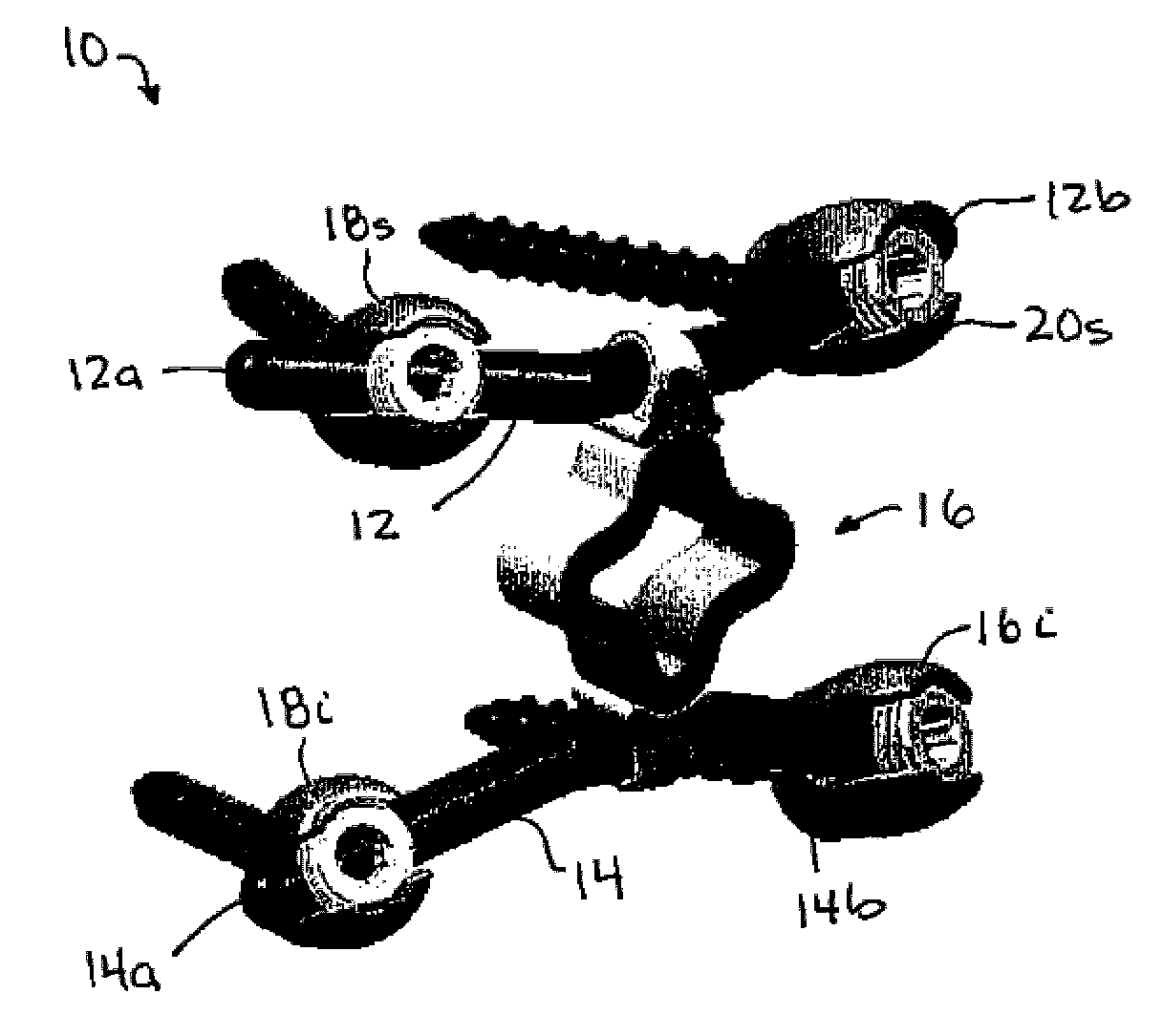
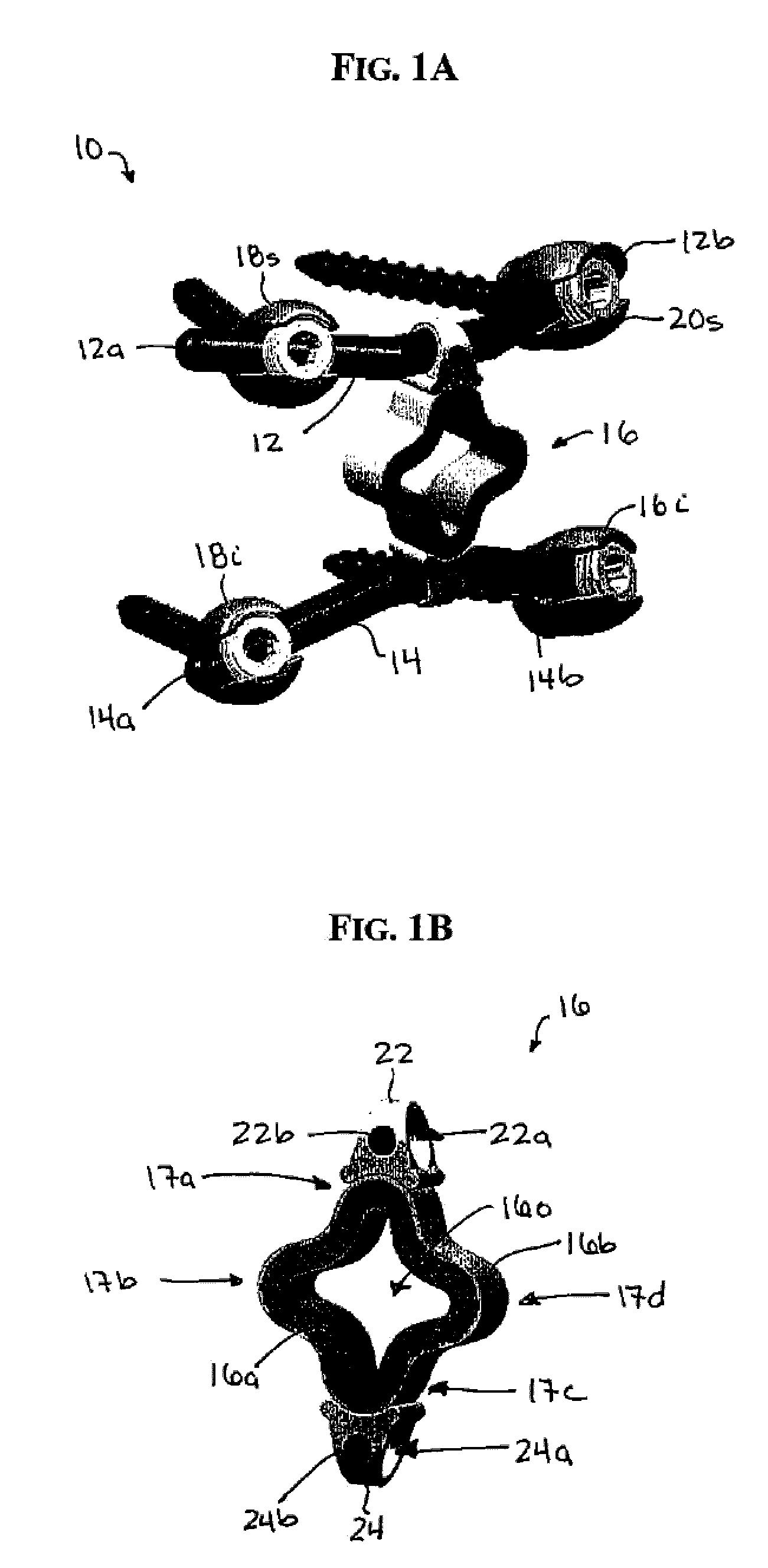
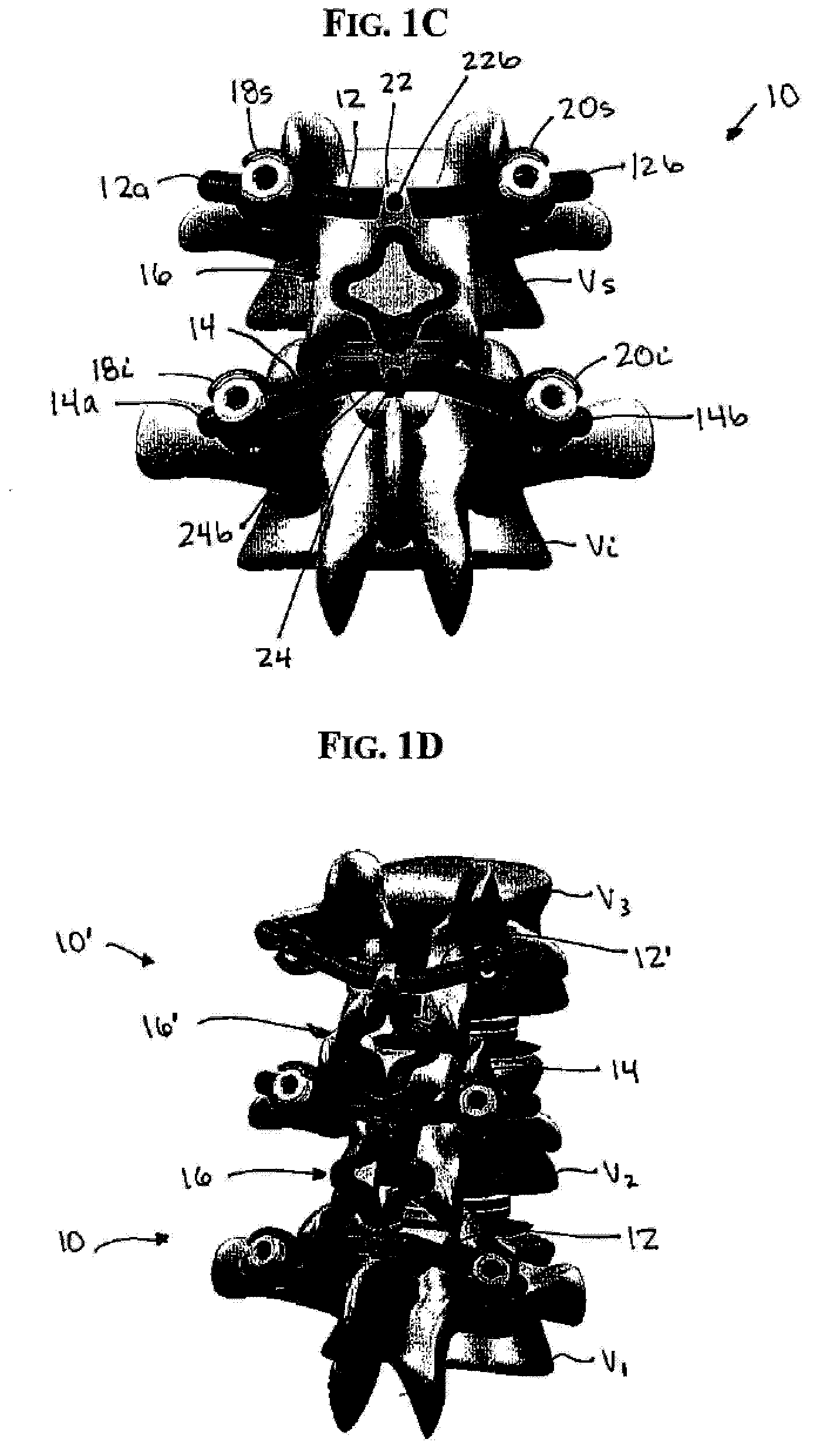
[0047]FIGS. 1A-1C illustrate one exemplary embodiment of a spinal stabilization device. As shown, the device 10 generally includes a first cross-connector 12 that is adapted to mate to opposed later...


PUM


Abstract

Various methods and devices are provided for stabilizing adjacent vertebrae in a patient's spinal column. In one exemplary embodiment, a spinal stabilization device is provided having a first cross-connector that is adapted to mate to opposed lateral sides of a first vertebra, a second cross-connector that is adapted to mate to opposed lateral sides of a second vertebra, and a flexible member that is coupled to the first and second cross-connectors and that is adapted to allow movement between first and second adjacent vertebrae coupled to the first and second cross-connectors.

Description

BACKGROUND OF THE INVENTION [0001] The vertebrae in a patient's spinal column are linked to one another by the disc and the facet joints, which control movement of the vertebrae relative to one another. Each vertebra has a pair of articulating surfaces located on the left side, and a pair of articulating surfaces located on the right side, and each pair includes a superior articular surface, which faces upward, and an inferior articular surface, which faces downward. Together the superior and inferior articular surfaces of adjacent vertebra form a facet joint. Facet joints are synovial joints, which means that each joint is surrounded by a capsule of connective tissue and produces a fluid to nourish and lubricate the joint. The joint surfaces are coated with cartilage allowing the joints to move or articulate relative to one another. [0002] Diseased, degenerated, impaired, or otherwise painful facet joints and / or discs can require surgery to restore function to the three joint compl...

Claims


Application Information

Patent Timeline
IPC IPC(8): A61B17/70
CPCA61B17/7023A61B17/7026A61B17/7043A61B17/7031A61B17/7028
Inventor KWAK, SEUNGKYU DANIELBURKE, ANDREABORGSTROM, AMIEHAWKINS, JOHN RILEYDUNBAR, WILLIAM
Owner DEPUY SPINE INC (US)
Why Eureka
Try Eureka