Method of securing programmable logic configuration data

a technology of configuration data and programmable logic, applied in the field of securing configuration data for programmable logic, can solve the problems of compensation for the system designer, configuration data must be transferred, or downloaded, and configuration data may be copied and used to configure plds,

Inactive Publication Date: 2007-03-29
CARNEGIE MELLON UNIV
View PDF18 Cites 48 Cited by
  • Summary
  • Abstract
  • Description
  • Claims
  • Application Information

AI Technical Summary

Problems solved by technology

The configuration of such devices into design-specific chips is thus “soft,” or ephemeral, and does not reflect a permanent alteration of physical structures within the chip.
A well-recognized problem with FPGAs, that is also present with VHAs, is that configuration data must be transferred, or downloaded, to the programmable logic device, at least as often as every power-up.
Since the configuration data often embodies the intellectual property that represents the value added to the system, a significant danger is that the configuration data may be copied and used to configure PLD's in unauthorized or “bootleg” systems, without compensating the system designer.
This solution is costly, and precludes the economies of scale available by using system memory to store configuration data as well as perform other system functions.
The encrypted configuration data may be freely distributed, as it is useless without a specific decryption key.
While this approach is sufficient to defeat the casual or unsophisticated copier, both the encrypted configuration data and the decryption key reside within the software of the system in the field.
While this greatly enhances security, it dramatically increases the cost of the PLO, and hence the system, since each PLD for a particular system must be separately configured, and subsequently tracked as a customized part.
Various other key distribution methodologies, such as third-party key management, introduce additional inefficiencies and increase costs.

Method used


Image

  • Method of securing programmable logic configuration data
  • Method of securing programmable logic configuration data
  • Method of securing programmable logic configuration data

Examples


Embodiment Construction

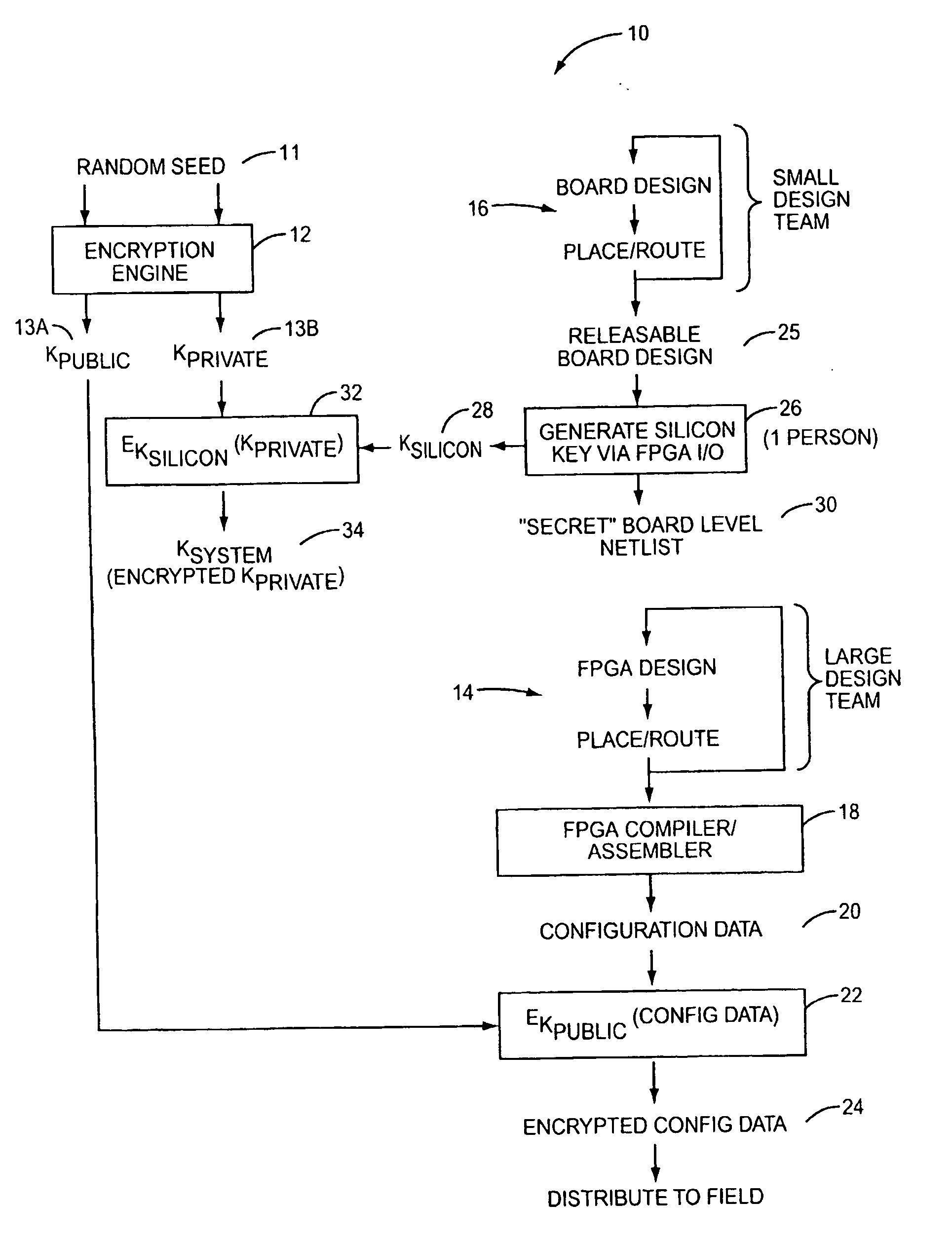
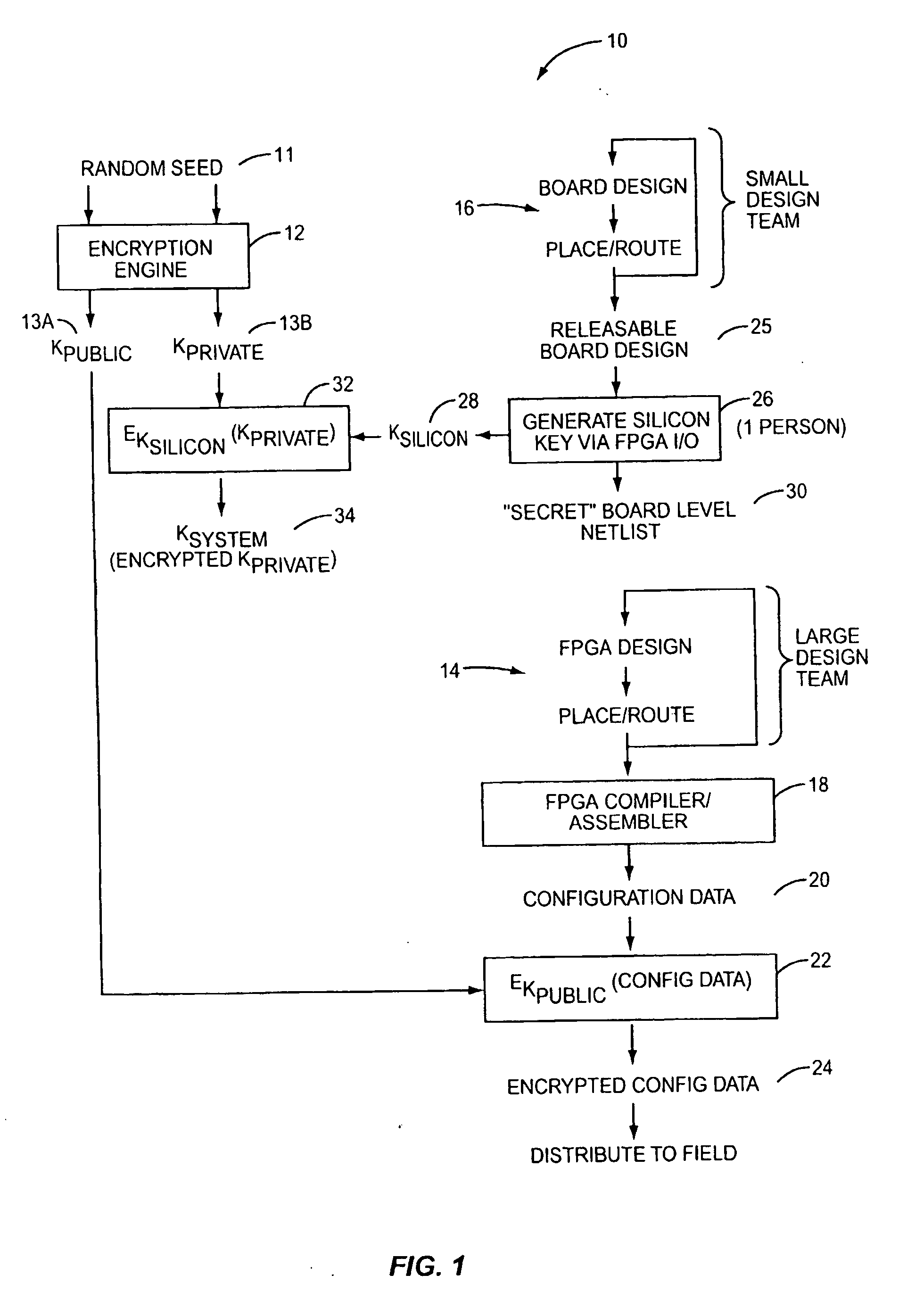
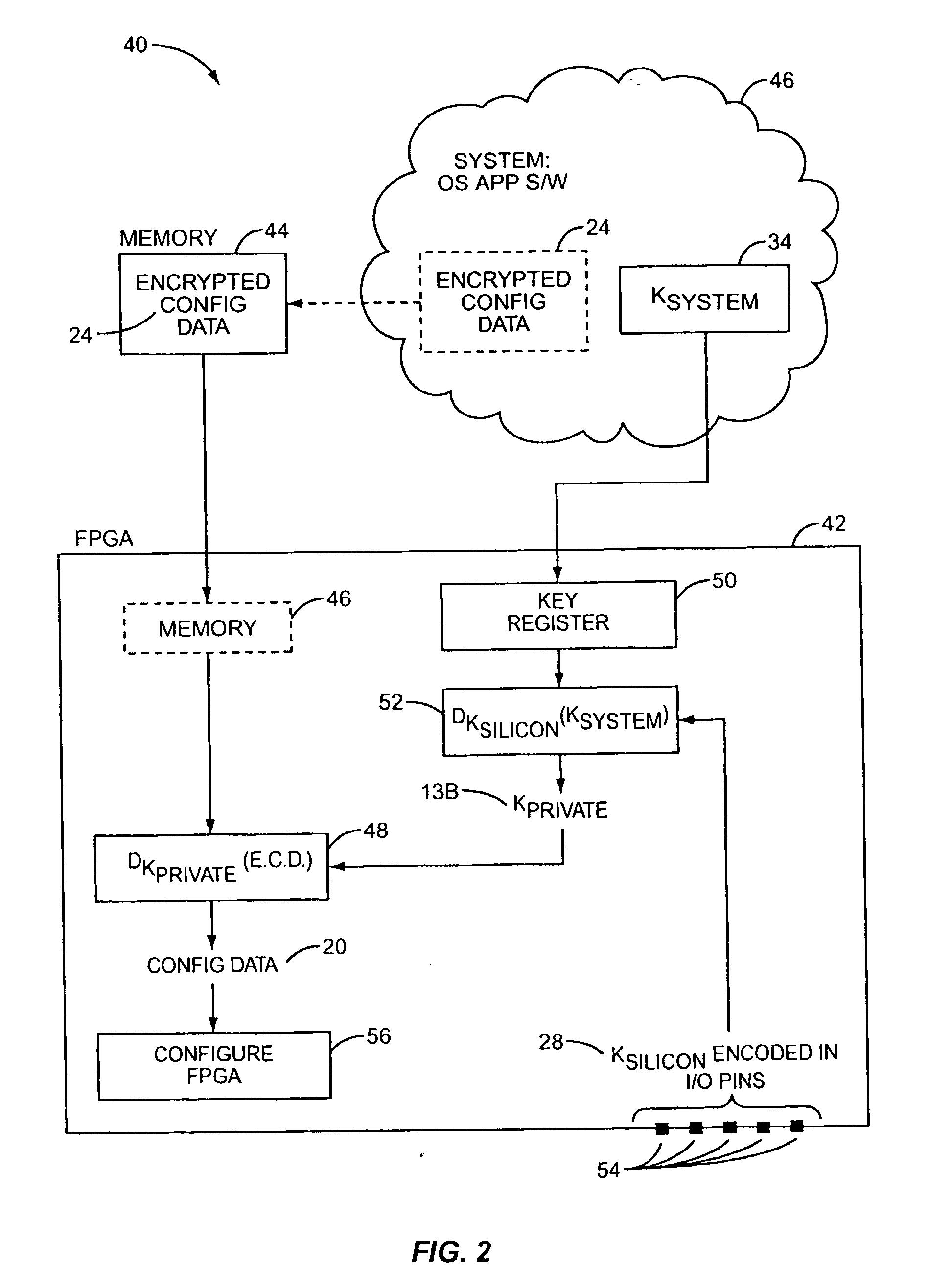
[0016] According to the present invention, configuration data for a Programmable Logic Device (PLD) is securely distributed to, and utilized in, field-deployed digital systems. That is, the configuration data is supplied in a format and according to a procedure that prevents the configuration data from being intercepted or copied in a usable form. This is accomplished by encrypting the configuration data prior to distribution. An associated decryption key is also encrypted, with a silicon key. The decryption key is recovered within the PLD from the system key, and the configuration data is decrypted on-board the PLD prior to its use in configuring the PLD's logic circuits and interconnect.

[0017] As used herein, the term Programmable Logic Device (PLD) refers broadly to a class of general-purpose digital circuits whose internal logical structure, interconnection, and / or pin-out—and hence the circuit's logic function—are specified by system designers in the form of configuration data...


PUM


Abstract

The present invention relates to a secure method of distributing configuration data for a programmable logic device (PLD). The configuration data is encrypted to generate encrypted configuration data. A decryption key is encrypted using a silicon key. The encrypted configuration data and the encrypted decryption key are transferred to a PLD. Within the PLD, the encrypted decryption key is decrypted using the silicon key. Then, also within the PLD, the encrypted configuration data is decrypted using the decryption key to recover the configuration data. The PLD is then configured using the configuration data. The silicon key may be communicated to the PLD by tying predetermined input pins to an active high voltage level or signal ground, to form a binary code.

Description

CROSS-REFERENCE TO RELATED APPLICATION [0001] This application is a divisional of co-pending U.S. patent application Ser. No. 10 / 260,171, filed 30 Sep. 2002, and entitled “Method of Securing Programmable Logic Configuration Data.”BACKGROUND OF INVENTION [0002] The present invention relates generally to the field of programmable logic and specifically to a method of securing configuration data for programmable logic. [0003] The use of Programmable Logic Devices (PLD) in modern digital electronics is well known and widely practiced. PLDs are a class of general-purpose integrated circuit devices that can be configured for a wide variety of functions and applications. In general, PLDs comprise an array of logic elements and variable interconnection paths between the logic elements and the chip I / O. At least the interconnections, and in more complex PLDs the logic blocks and I / O pins as well, are programmable, allowing a system designer to implement a broad array of functions ranging fro...

Claims


Application Information

Patent Timeline
Patent Type & Authority Applications(United States)
IPC IPC(8): G06F12/14
CPCH04L63/0428H04L2463/062H04L2209/125H04L9/0897Y04S40/24Y04S40/20
Inventor VAN ESSEN, BRIAN CHRISTOPHERKIDD, JEFFREY WAYNEPETERSEN, CHRISTOPHER MAVERICKSCHMIT, HERMAN H.
Owner CARNEGIE MELLON UNIV
Why Eureka
Try Eureka