Programmable microelectronic device, structure, and system and method of forming the same

a microelectronic device and programmable technology, applied in nanoinformatics, instruments, transistors, etc., can solve the problems of significant chip area increase, data loss, and particularly volatile dynamic ram (“dram”), so as to reduce the cross-sectional area of the interface, reduce the interface area, and increase the efficiency of the device

Inactive Publication Date: 2006-01-10
AXON TECH
View PDF6 Cites 147 Cited by
  • Summary
  • Abstract
  • Description
  • Claims
  • Application Information

AI Technical Summary

Benefits of technology

[0014]The ways in which the present invention addresses various drawbacks of now-known programmable devices are discussed in greater detail below. However, in general, the present invention provides a programmable device that is relatively easy and inexpensive to manufacture, which is relatively easy to program, and which can be variably programmed.
[0018]In accordance with another embodiment of the present invention, at least a portion of a programmable structure is formed within a through-hole or via in an insulating material. In accordance with one aspect of this embodiment, a first electrode feature is formed on a surface of a substrate, insulating material is deposited onto a surface of the electrode feature, a via is formed within the insulating material, and a portion of the programmable structure is formed within the via. After the via is formed within the insulating material, a portion of the structure within the via is formed by depositing an ion conductive material onto the conductive material, depositing a second electrode material onto the ion conductive material, and, if desired, removing any excess electrode, ion conductor, and / or insulating material. In accordance with another aspect of this embodiment, only the ion conductor is formed within the via. In this case, a first electrode is formed below the insulating material and in contact with the ion conductor and the second electrode is formed above the insulating material and in contact with the ion conductor. The configuration of the via may be changed to alter (e.g., reduce) a contact area between one or more of the electrodes and the ion conductor. Reducing the cross-sectional area of the interface between the ion conductor and the electrode increases the efficiency of the device (change in electrical property per amount of power supplied to the device). In accordance with another aspect of this embodiment, the via may extend through the lower electrode to reduce the interface area between the electrode and the ion conductor. In accordance with yet another aspect of this embodiment, a portion of the ion conductor may be removed from the via or the ion conductor material may be directionally deposited into only a portion of the via to further reduce an interface between an electrode and the ion conductor.
[0019]In accordance with another embodiment of the invention, a programmable device may be formed on a surface of a substrate. In accordance with one aspect of this embodiment, the substrate includes a microelectronic circuit. In accordance with a further aspect of this embodiment, the memory device is formed overlying the microelectronic circuit and conductive lines between the microelectronic circuit and the memory are formed using conductive wiring schemes within the substrate and the memory device. This configuration allows transmission of more bits of information per bus line.

Problems solved by technology

Dynamic RAM (“DRAM”) is particularly volatile in that it must be “refreshed” (i.e., recharged) every few hundred milliseconds in order to maintain the stored data.
Static RAM (“SRAM”) will hold the data after one writing so long as the power source is maintained; once the power source is disconnected, however, the data is lost.
Thus, in these volatile memory configurations, information is only retained so long as the power to the system is not turned off In general, these RAM devices can take up significant chip area and therefore may be expensive to manufacture and consume relatively large amounts of energy for data storage.
Other storage devices such as magnetic storage devices (e.g., floppy disks, hard disks and magnetic tape) as well as other systems, such as optical disks, CD-RW and DVD-RW are non-volatile, have extremely high capacity, and can be rewritten many times. Unfortunately, these memory devices are physically large, are shock / vibration-sensitive, require expensive mechanical drives, and may consume relatively large amounts of power.
These negative aspects make such memory devices non-ideal for low power portable applications such as lap-top and palm-top computers, personal digital assistants (“PDAs”), and the like.
Once programmed, the WORM device cannot be reprogrammed.
Thus, such devices are generally not well suited for use in portable electronic devices.
EEPROM devices are generally easier to program, but suffer from other deficiencies.
In particular, EEPROM devices are relatively complex, are relatively difficult to manufacture, and are relatively large.
Consequently, EEPROM cost per bit of memory capacity is extremely high compared with other means of data storage.
Another disadvantage of EEPROM devices is that, although they can retain data without having the power source connected, they require relatively large amounts of power to program.
This power drain can be considerable in a compact portable system powered by a battery.
Forming memory devices and the microprocessor on separate substrates may be undesirable for several reasons.
For example, forming various types of memory on separate substrate may be relatively expensive, may require relatively long transmission paths to communicate between the memory devices and any associated electronic device, and may require a relatively large amount of room within a system.

Method used


Image

  • Programmable microelectronic device, structure, and system and method of forming the same
  • Programmable microelectronic device, structure, and system and method of forming the same
  • Programmable microelectronic device, structure, and system and method of forming the same

Examples


Embodiment Construction

[0039]The present invention generally relates to programmable microelectronic devices, to systems including the devices, and to methods of forming the devices and systems.

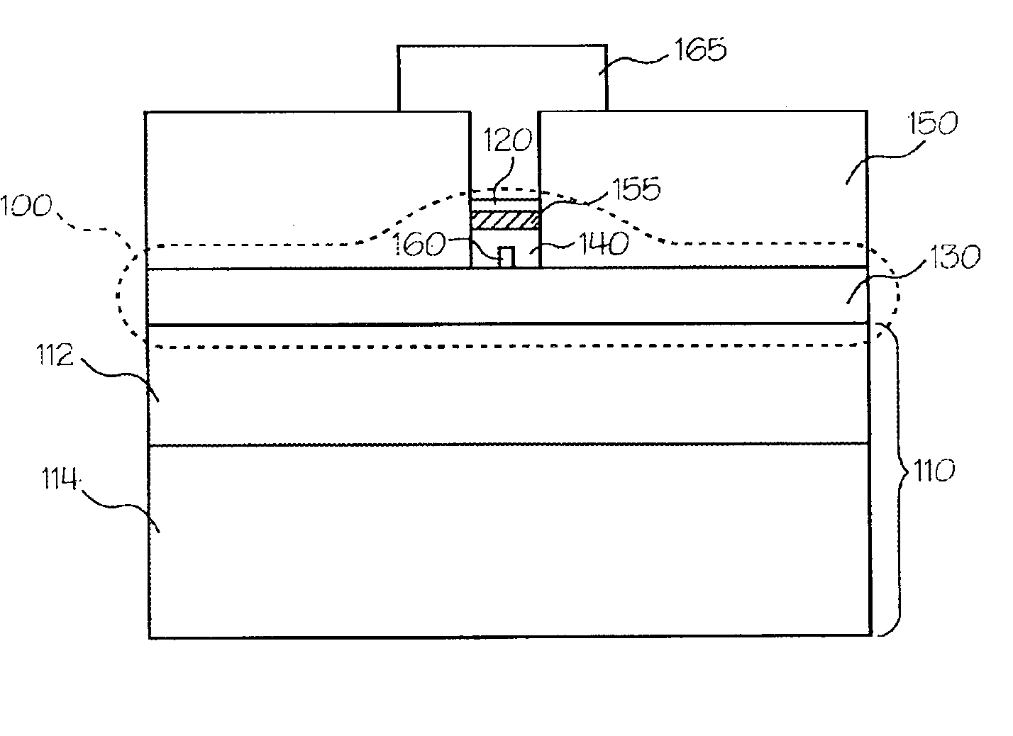
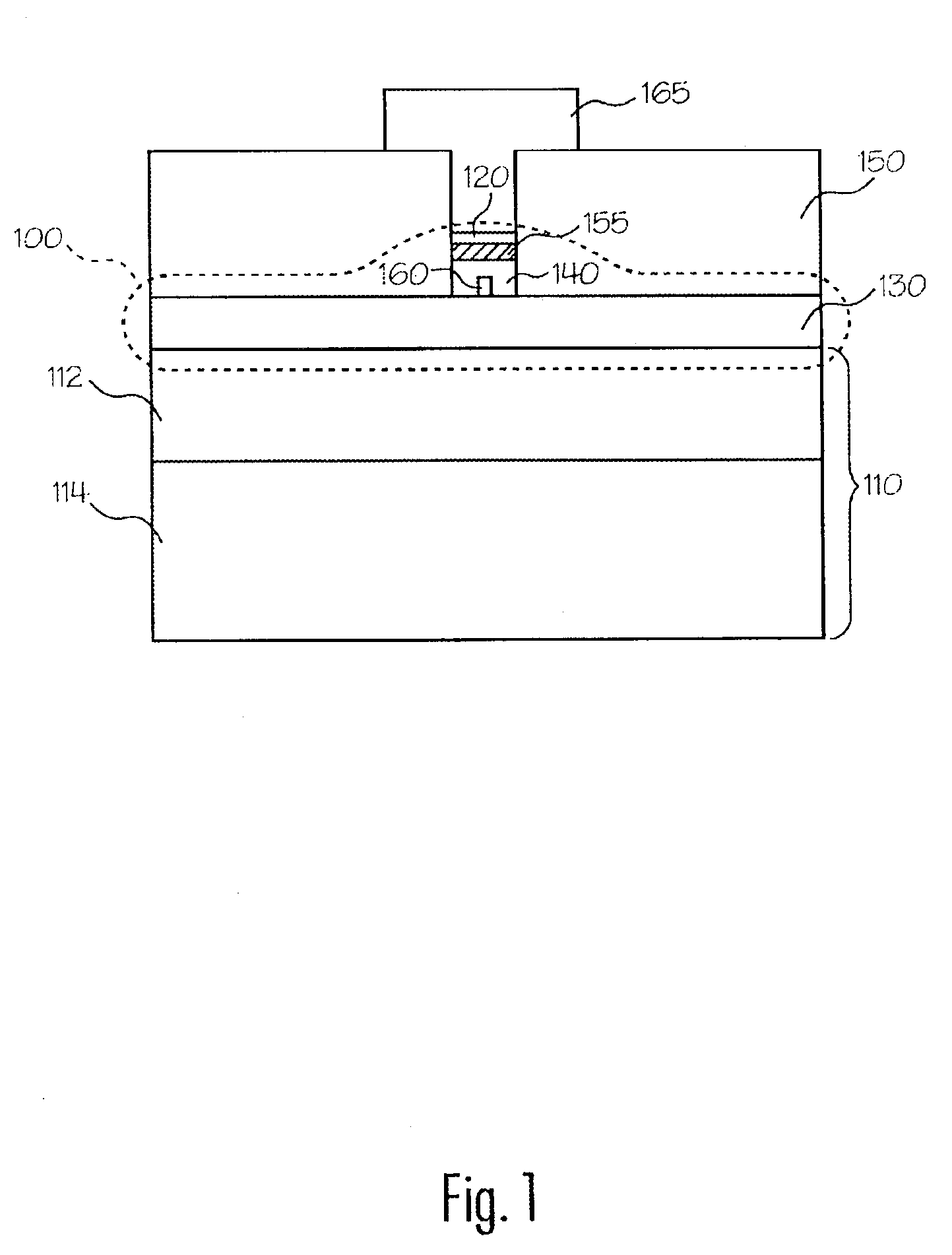
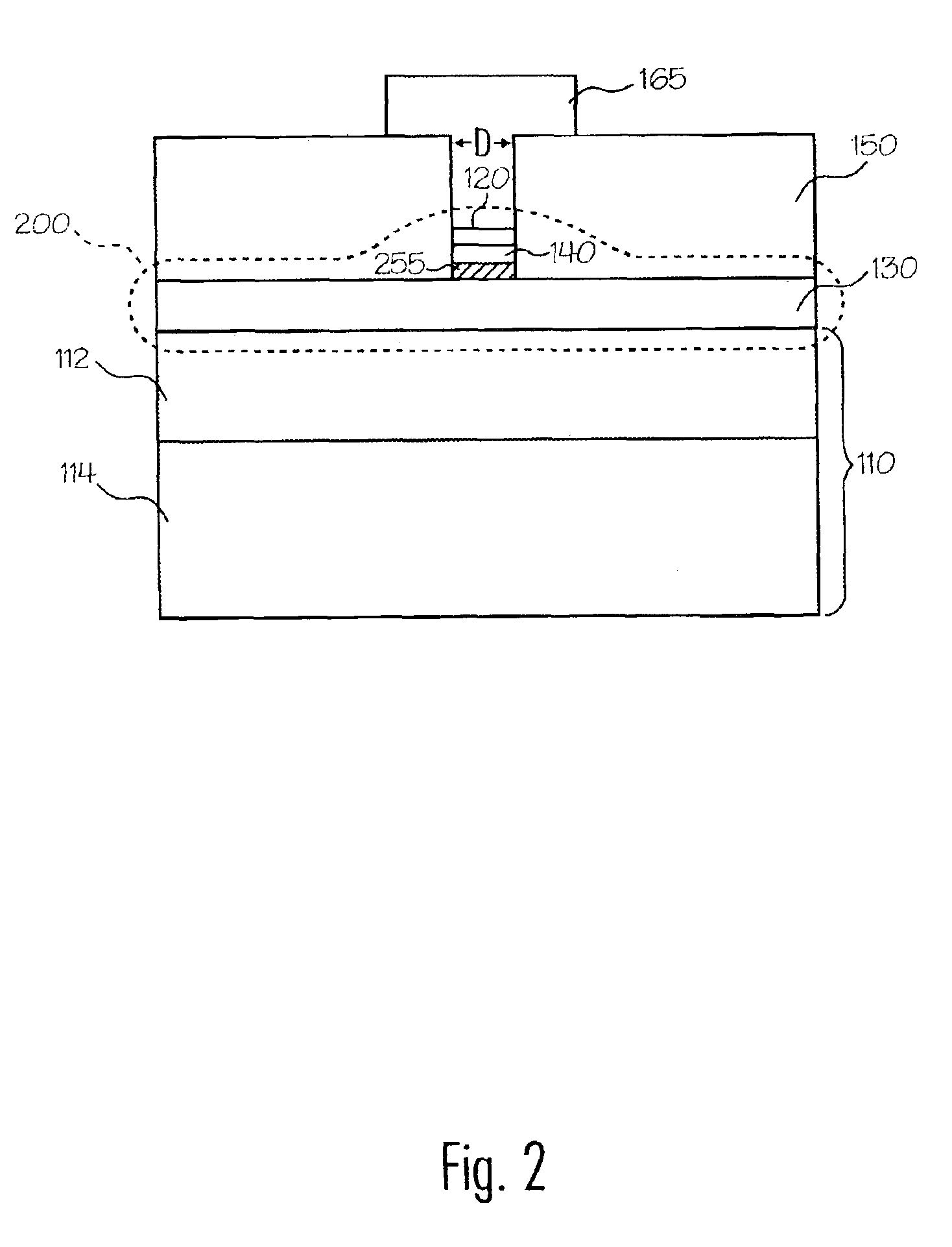
[0040]FIGS. 1 and 2 illustrate programmable microelectronic structures 100 and 200 formed on a surface of a substrate 110 in accordance with an exemplary embodiment of the present invention. Structures 100 and 200 include electrodes 120 and 130, an ion conductor 140, and optionally include buffer or barrier layers or regions 155 and / or 255.

[0041]Generally, structures 100 and 200 are configured such that when a bias greater than a threshold voltage (VT), discussed in more detail below, is applied across electrodes 120 and 130, the electrical properties of structure 100 change. For example, in accordance with one embodiment of the invention, as a voltage V≧VT is applied across electrodes 120 and 130, conductive ions within ion conductor 140 begin to migrate and form a region 160 having an increased conductivity compa...


PUM


Abstract

A microelectronic programmable structure suitable for storing information and a method of forming and programming the structure are disclosed. The programmable structure generally includes an ion conductor and a plurality of electrodes. Electrical properties of the structure may be altered by applying energy to the structure, and thus information may be stored using the structure.

Description

CROSS REFERENCE TO RELATED APPLICATIONS[0001]This application is a continuation-in-part of U.S. patent application Ser. No. 10 / 118,276 entitled MICROELECTRONIC DEVICE, STRUCTURE, AND SYSTEM, INCLUDING A MEMORY STRUCTURE HAVING A VARIABLE PROGRAMMABLE PROPERTY AND METHOD OF FORMING SAME, filed Apr. 8, 2002 now U.S. Pat. No. 6,825,489, which is a continuation-in-part of application Ser. No. 09 / 502,915, entitled PROGRAMMABLE MICROELECTRONIC DEVICES AND METHODS OF FORMING AND PROGRAMMING SAME, filed Feb. 11, 2000, now U.S. Pat. No. 6,487,106; and is a continuation-in-part of U.S. patent application Ser. No. 09 / 951,882, entitled MICROELECTRONIC PROGRAMMABLE DEVICE AND METHODS OF FORMING AND PROGRAMMING THE SAME, filed Sep. 10, 2001, now U.S. Pat. No. 6,635,914; and claims the benefit of U.S. Patent Application Ser. No. 60 / 327,899, entitled OXIDE-BASED SOLID ELECTROLYTE FOR THE PROGRAMMABLE METALLIZATION CELL, filed Oct. 9, 2001, U.S. Patent Application Ser. No. 60 / 337,211, entitled HIGH ...

Claims


Application Information

Patent Timeline
Patent Type & Authority Patents(United States)
IPC IPC(8): G11C11/00G11C11/56G11C13/02G11C16/02H01L27/10H01L27/24H01L45/00
CPCB82Y10/00H01L45/124G11C13/0011G11C13/0069H01L27/101H01L45/085H01L45/12H01L45/1233H01L45/1253H01L45/1266H01L45/142H01L45/143H01L45/144H01L45/145H01L45/146H01L45/1625H01L45/1641H01L45/1683H01L45/1691G11C11/5614G11C13/04G11C2013/009G11C2207/104G11C2213/15G11C2213/34G11C2213/51G11C2213/72G11C2213/79H01L27/2409H01L27/2436H10B63/20H10B63/30H10N70/801H10N70/245H10N70/8265H10N70/841H10N70/8416H10N70/8822H10N70/8825H10N70/883H10N70/026H10N70/041H10N70/068H10N70/066H10N70/8828H10N70/8833H10N70/826
Inventor KOZICKI, MICHAEL N.
Owner AXON TECH
Why Eureka
Try Eureka