Motor frame having embedded cooling coil

a technology of cooling coil and motor frame, which is applied in the direction of supporting/enclosing/casing, dynamo-electric machines, electrical equipment, etc., can solve the problems of increasing the time, labor and expense of producing such motors and other devices, affecting the proper operation of the motor or other device, and other devices creating more heat than can be effectively dissipated

Inactive Publication Date: 2007-04-05
RELIANCE ELECTRIC TECH
View PDF4 Cites 22 Cited by
  • Summary
  • Abstract
  • Description
  • Claims
  • Application Information

AI Technical Summary

Benefits of technology

[0006] In accordance with certain embodiments, the present technique provides a device component having a cooling coil embedded in a cast body of the component. The cooling coil includes an internal conduit or passage for transmission of a cooling material through the cooling coil. The cooling coil material has a melting point substantially equal to or less than the melting point of the material of the cast body. Heat is transferred from the device to the cooling material and is thereby removed from the component. The cooling material may be any material with suitable thermal characteristics, including various fluids or gases. By way of example, the device component may be a motor frame having a serpentine or helical cooling coil.

Problems solved by technology

As will be appreciated, transmission of electricity through the windings of a motor, or the circuitry of an electronic device, and friction between moving and stationary components within devices generate heat, which may interfere with proper operation of the motor or other device.
While some devices may adequately dissipate such heat through passive cooling techniques, other devices create more heat than can be effectively dissipated through such techniques.
However, inclusion of active cooling systems increases the time, labor, and expense of producing such motors and other devices.

Method used


Image

  • Motor frame having embedded cooling coil
  • Motor frame having embedded cooling coil
  • Motor frame having embedded cooling coil

Examples


Embodiment Construction

[0015] As discussed in detail below, certain embodiments of the present invention provide components, apparatus, and methods for motors and motor construction. Although the following discussion focuses on induction motors, the present invention also affords benefits to a number of applications, including not only those involving other types of electric motors, such as direct current (dc) motors, or rotating machines, but also those involving heat-generating devices outside the field of motors and rotating machines. Accordingly, the following discussion provides exemplary embodiments of the present invention and, as such, should not be viewed as limiting the appended claims to the embodiments described.

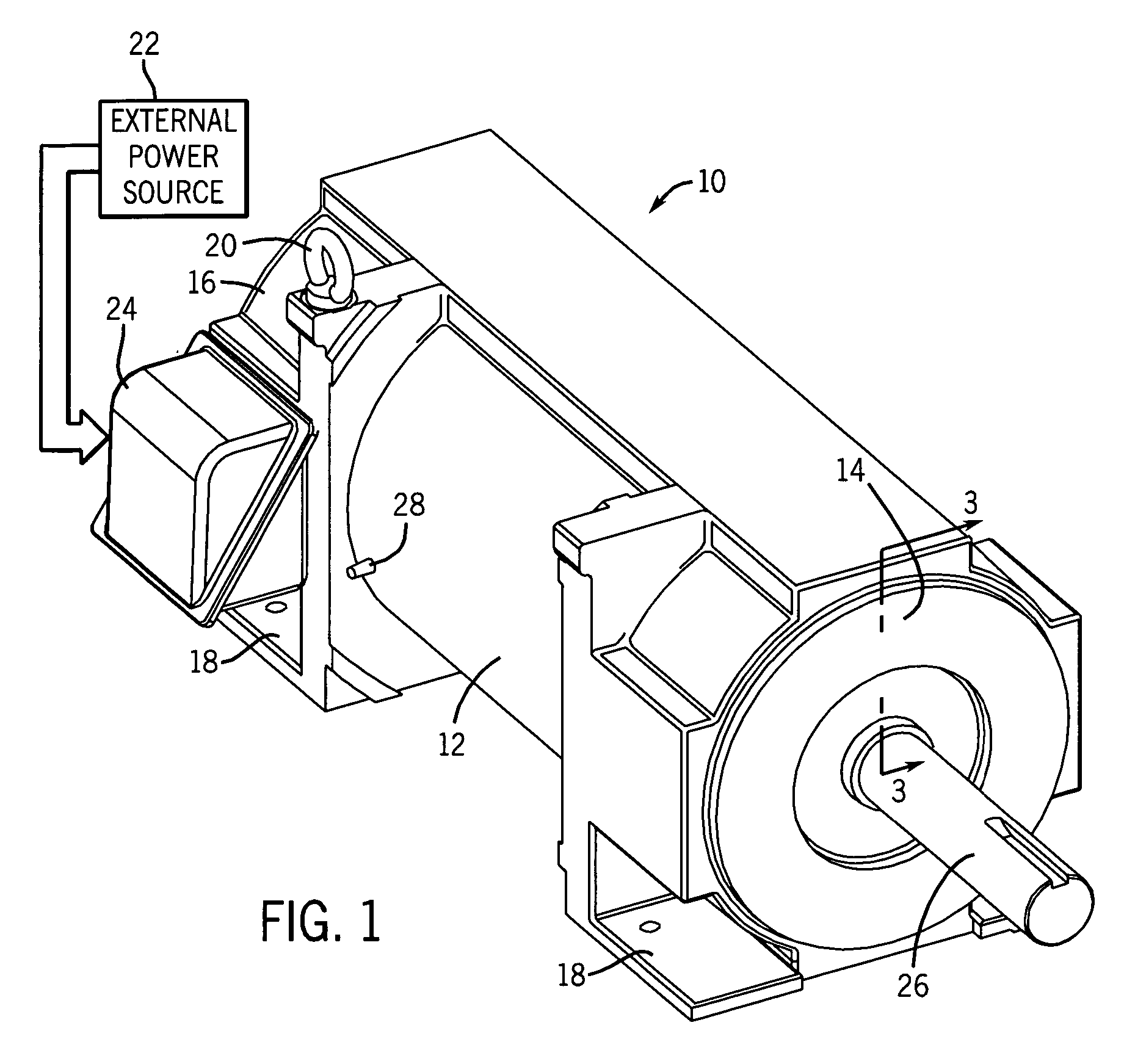
[0016] Turning to the drawings, FIG. 1 illustrates an exemplary electric motor 10. In the embodiment illustrated, the motor 10 comprises an induction motor housed in a National Electrical Manufacturers' Association (NEMA) motor housing. As appreciated by those of ordinary skill in the...


PUM


Abstract

A method of manufacturing an apparatus, such as a motor or other rotating machine, having a cooling coil is provided. The exemplary method includes disposing a cooling coil within a casting mold and casting a component of the device such that the cooling coil is embedded within the component. A coolant is routed through the cooling coil during the casting process to reduce or prevent melting of the cooling coil and preserve a fluid conduit within the cooling coil. A device component and apparatus having a cooling coil are also provided.

Description

BACKGROUND [0001] The present invention generally relates to heat-generating devices and machines, including rotating machines such as electric induction motors. More particularly, the present invention relates to a technique for embedding a cooling coil or conduit in a device or machine component to promote heat dissipation from the device or machine. [0002] Rotating machines of various types are commonly found in industrial, commercial and consumer settings. For instance, in industry, motors are employed to drive various kinds of machinery, such as pumps, conveyors, compressors, fans and so forth, to mention only a few. Conventional alternating current (ac) electric motors may be constructed for single- or multiple-phase power, and are typically designed to operate at predetermined speeds or revolutions per minute (rpm), such as 3600 rpm, 1800 rpm, 1200 rpm, and so on. Such motors generally include a stator comprising a multiplicity of windings surrounding a rotor, which is suppor...

Claims


Application Information

Patent Timeline
Patent Type & Authority Applications(United States)
IPC IPC(8): H02K3/24H02K9/00
CPCH02K5/20H02K15/14H02K5/203
Inventor NARAYANAN, RAJMOHANDONG, QIMIN J.
Owner RELIANCE ELECTRIC TECH
Why Eureka
Try Eureka