Antenna sharing device and wireless communication terminal using the same

Inactive Publication Date: 2006-06-29
HITACHI MEDIA ELECTORONICS CO LTD
View PDF6 Cites 31 Cited by
  • Summary
  • Abstract
  • Description
  • Claims
  • Application Information

AI Technical Summary

Benefits of technology

[0017] According to the present invention, a compa

Problems solved by technology

Unifying such various multiplex systems, however, appears difficult.
Adding new functional units to a mobile phone makes its circuit more complicated and increases the number of its components.
The antenna sharing devices disclosed in US 2004/0240420 A1 and Japanese Patent Laid-Open No. 2004-40322, however, incorporate no technical ingenuity in connection with the transmitter distortion specified for the WCDMA system.
With such antenna shar

Method used


Image

  • Antenna sharing device and wireless communication terminal using the same
  • Antenna sharing device and wireless communication terminal using the same
  • Antenna sharing device and wireless communication terminal using the same

Examples


embodiment 1

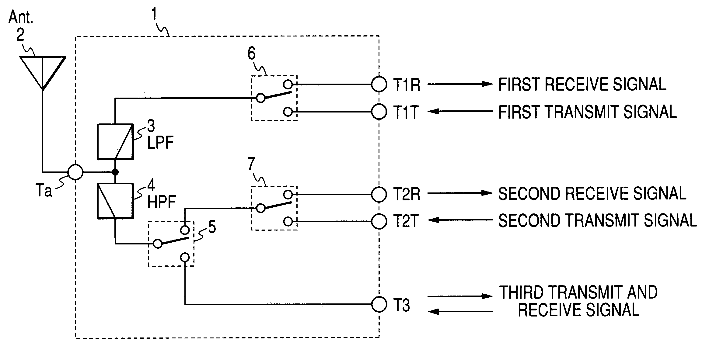
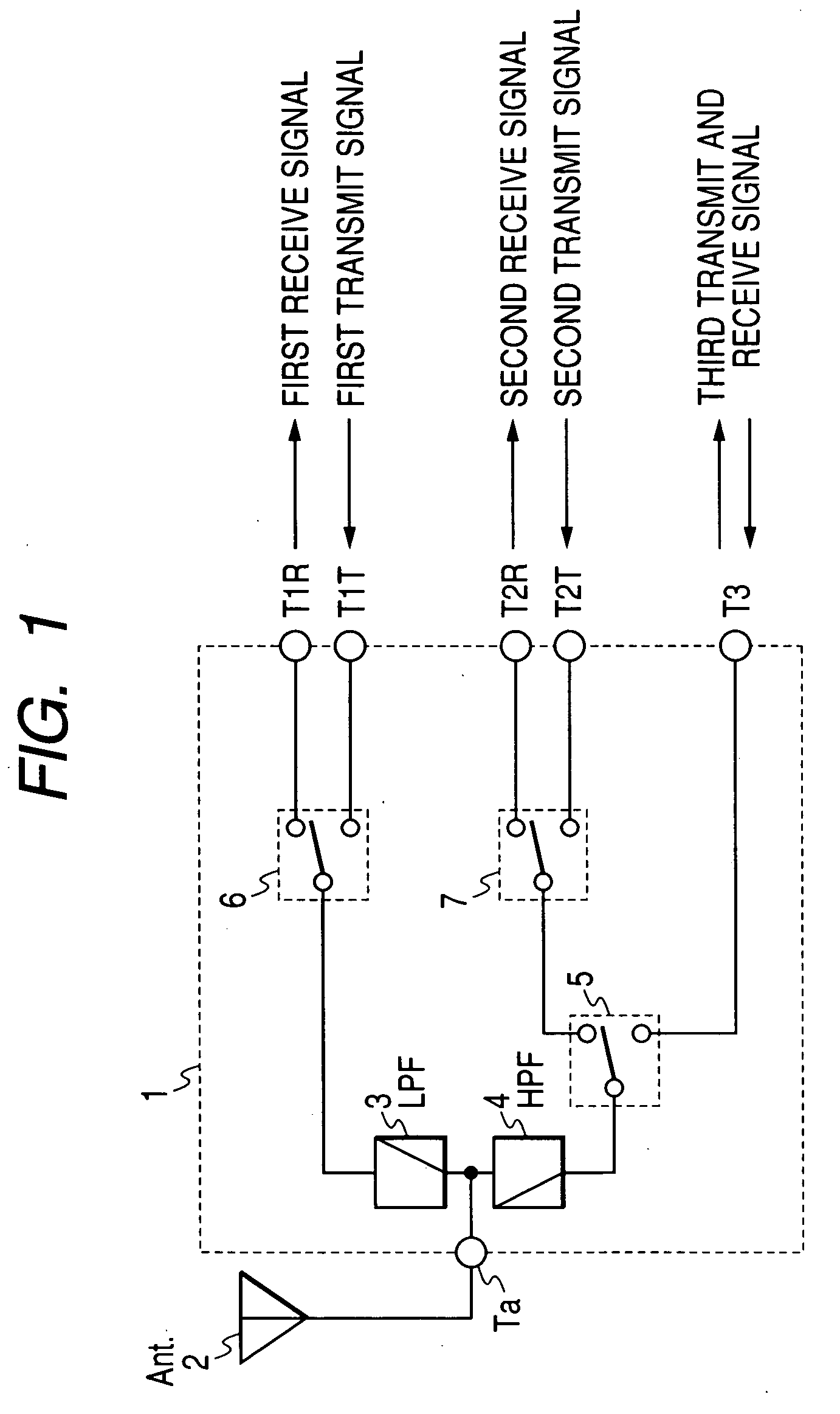
[0034] First, a most basic configuration of an antenna sharing device as shown in FIG. 1 will be described as a first embodiment of the present invention. Referring to FIG. 1, it is considered important to use appropriate combinations of signal bands, indicated as the first, second and third transmit and receive signals in FIG. 1, and communication systems; for example, combinations of the first signal band and a GSM (Global System for Mobile Communications) system, the second signal band and a DCS (Digital Cellular System) system, and the third signal band and a WCDMA (Wideband Code Division Multiple Access) system.

[0035] The present embodiment will be described based on the above three combinations. The transmit signal frequency band and receive signal frequency band used by the GSM system are from 880 MHz to 915 MHz and from 925 MHz to 960 MHz, respectively. The transmit signal frequency band and receive signal frequency band used by the DCS system are from 1710 MHz to 1785 MHz ...

embodiment 2

[0078] Next, a second embodiment of the present invention will be described with reference to FIG. 9. In the configuration shown in FIG. 9, a GSM receive filter 8, a DCS receive filter 9, and a WCDMA diplexer in which a CDMA receive filter 10 and a WCDMA transmit filter 11 are connected in parallel are disposed downstream of the switches.

[0079] These filters may comprise a combination of SAW (Surface Acoustic Wave), FBAR (Filmed Bulk Acoustic Resonator) and SMR (Solidly Mounted Resonator) filters.

[0080] The present embodiment, like the first embodiment, can provide an inexpensive and practical antenna sharing device which meets requirements in terms of transmitter distortion characteristic and ESD resistivity.

embodiment 3

[0081] Next, a third embodiment of the present invention will be described. In introducing the first and second embodiments of the present invention, superiority of the present invention was described based on, for simplicity of explanation, a dual-mode, triple-band configuration for using GSM, DCS and WCDMA signals.

[0082] However, it is not only when a dual-mode, triple-band configuration is used that the superiority of the present invention is effective. The present invention is as effective as in the first and second embodiments also when a dual-mode, quintet band configuration is used.

[0083] Namely, it is effective also when a dual-mode, quintet band configuration as shown in FIG. 10 is used with the configuration including a GSM filter circuit (8-1) and a GSM-850 filter circuit (8-2) connected in parallel downstream of a high-frequency switch 6, a DCS filter circuit (9-1) and a PCS filter circuit (9-2) connected in parallel downstream of a high-frequency switch 7, and a WCDMA...


PUM


Abstract

A compact, inexpensive antenna sharing device meeting requirements in terms of transmitter distortion characteristic and ESD characteristic is provided which separates and combines signals transmitted and received in first to third signal bands and which thereby enables an antenna terminal to be shared as a common terminal. It includes a diplexer realizing an attenuation characteristic for protection against ESD, a compound semiconductor switch with an IIP3 of 66 dBm or more, and an inexpensive PIN diode switch.

Description

CLAIM OF PRIORITY [0001] The present application claims priority from Japanese application JP 2004-377250 filed on Dec. 27, 2004, the content of which is hereby incorporated by reference into this application. FIELD OF THE INVENTION [0002] The present invention relates to an antenna sharing device which, in a communication device such as a mobile phone, separates and combines transmit and receive signals, and thereby enables an antenna terminal to be put in shared use. BACKGROUND OF THE INVENTION [0003] An antenna sharing device for use with a dual-mode mobile phone compatible with GSM and W-CDMA systems has been known in which: a diplexer separates a frequency band for GSM and a frequency band for W-CDMA; transmit and receive signals in the GSM band are separated using a high-frequency switch for GSM; and transmit and receive signals in the W-CDMA band are separated using a duplexer for W-CDMA (see, for example, US Patent Application Publication No. 2004 / 0240420 A1). [0004] Another...

Claims


Application Information

Patent Timeline
IPC IPC(8): H04B1/44
CPCH04B1/006H04B1/48
Inventor SHIBAGAKI, NOBUHIKOHIKITA, MITSUTAKASAKIYAMA, KAZUYUKIHIKINO, OSAMU
Owner HITACHI MEDIA ELECTORONICS CO LTD
Why Eureka
Try Eureka