Electric power distribution device

a technology of power distribution device and power supply, which is applied in the direction of windings, dynamo-electric components, electric cable installations, etc., can solve the problems of increasing cost, increasing manpower and production costs, and increasing processing man-hours

Inactive Publication Date: 2007-04-05
YAZAKI CORP
View PDF4 Cites 32 Cited by
  • Summary
  • Abstract
  • Description
  • Claims
  • Application Information

AI Technical Summary

Problems solved by technology

Therefore, a processing man-hour increases and it becomes a problem about the cost.
Therefore, the manpower and the production cost increases.

Method used


Image

  • Electric power distribution device
  • Electric power distribution device
  • Electric power distribution device

Examples


first embodiment

[0040] A first embodiment of an electric power distribution device according to the present invention will be described with reference to Figures.

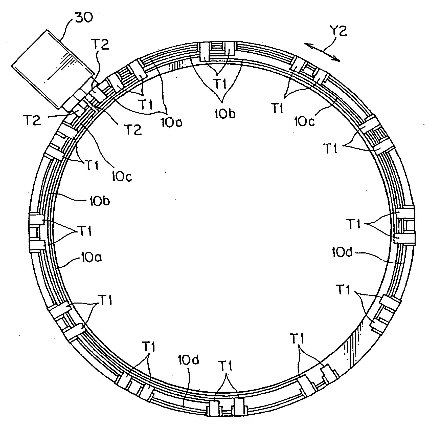
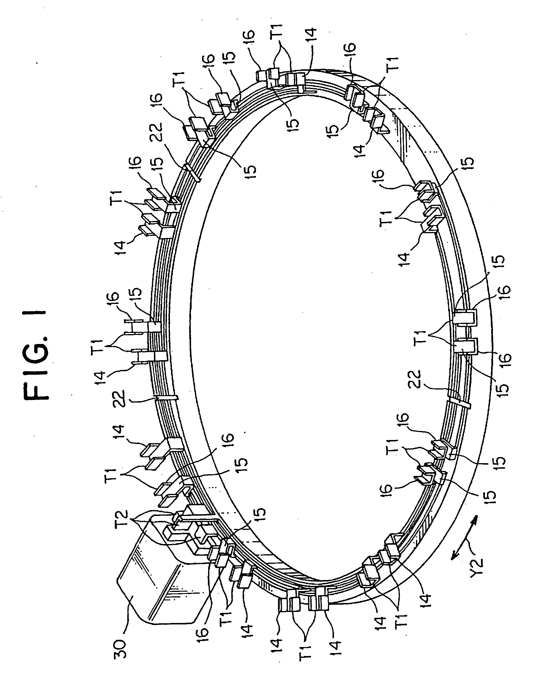
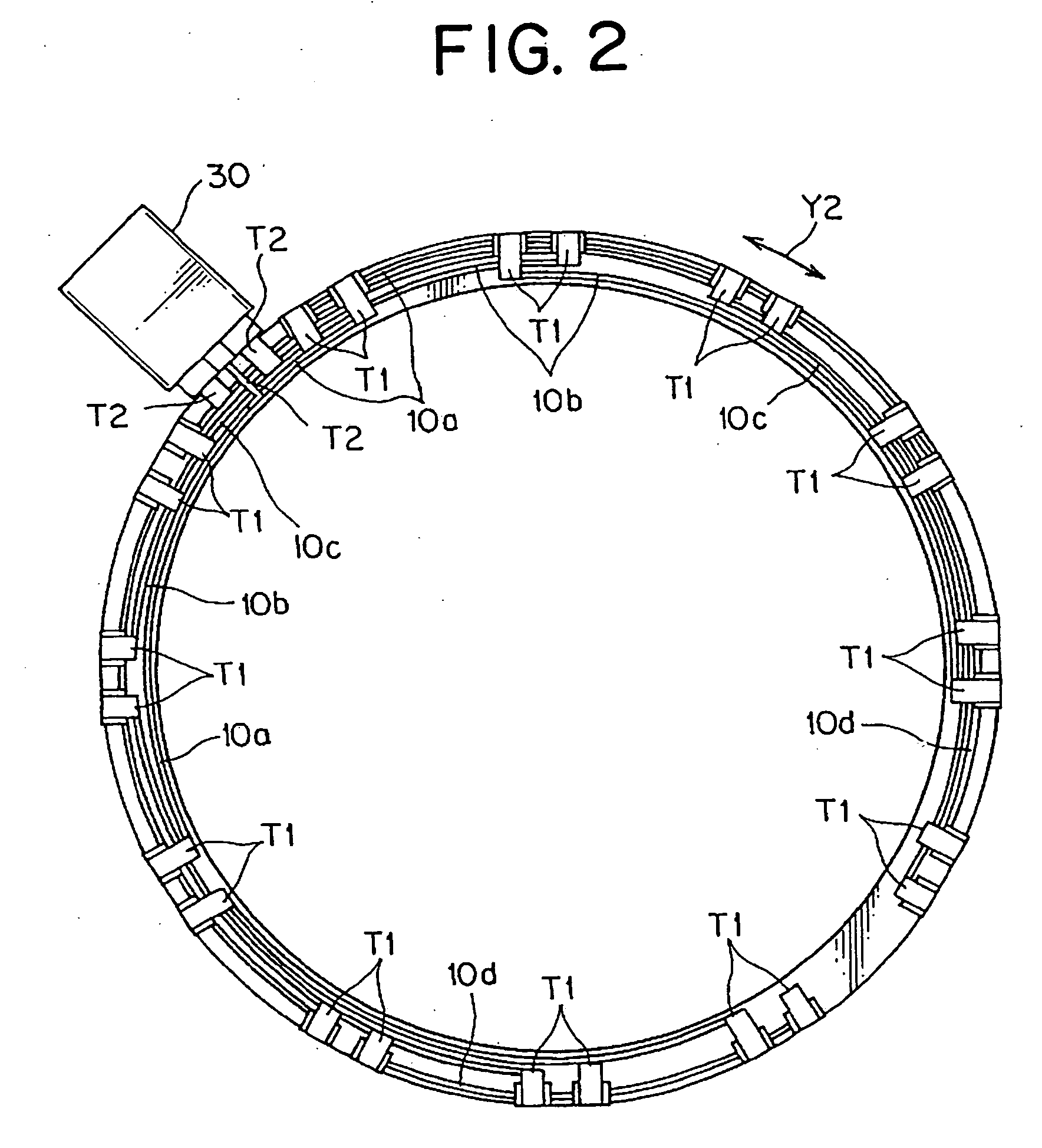
[0041] A brushless motor (not shown) generally includes a rotor connected directly with a motor rotation shaft, and a ring-shaped stator surrounding the rotor. Three-phase stator coils are wound around cores of the stator. The stator coils are arranged on a circle about the motor rotation shaft. In this embodiment, for example, twelve stator coils are wound around cores, and arranged at equal intervals on the circle about the motor rotation shaft. The electric power distribution device of the present invention is used for supplying electric power by connecting the stator coils L as shown in FIG. 8.

[0042] As shown in FIGS. 1 and 2, the electric power distribution device includes a plurality of band-shaped bus bars 10a to 10d (shown in FIG. 2), on which end coil terminals T1 are formed in a width direction Y1 for supplying electric power t...

second embodiment

[0065] Next, a second embodiment according to the present invention will be explained.

[0066] As shown in FIGS. 10 to 12, the electric power distribution device includes band-shaped bus bars 10a to 10d each in which the coil terminal T1 is formed on an end in the width direction Y1, and a insulating holder 20 on which receiving grooves 21e to 21f are formed. The coil terminal T1 supplies power to the stator coil L. The receiving grooves 21e to 21f receive the bus bars 10a to 10d in a manner that they are insulated from each other.

[0067] The coil terminal T1 and the power terminal T2 in the second embodiment respectively work the same as those in the first embodiment. As shown in FIG. 12, a plurality of flat parts 11 are formed on the band-shaped bus bars 10a to 10d, and a folded part 18 is interposed between the flat parts 11 adjacent to each other. In the band-shaped bus bars 10a to 10d, lengths L1 at the flat parts 11 except at both ends are equal to each other. Folding angles θ ...


PUM


Abstract

A band-shaped bus bar includes a flat part disposed at the center thereof, and a curved part at both ends in a length direction. A receiving groove for receiving the bus bar is extended along a circle in an insulating holder. The flat part of the bus bar is received in the receiving groove in a curved manner.

Description

CROSS REFERENCE TO RELATED APPLICATIONS [0001] This application is based on Japanese Patent Application No. 2005-292122, the contents of which are hereby incorporated by reference. BACKGROUND OF THE INVENTION [0002] 1. Field of the Invention [0003] The present invention relates to an electric power distribution device, in particular, to an electric power distribution device for supplying electric power to a stator coil that arranges on a motor-rotation axis centered circle. [0004] 2. Description of the Related Art [0005] Recently, needs for reducing the fuel cost of a vehicle has become large, and for example, a development of the super-low fuel consumption hybrid vehicle is under development. Especially recently, a hybrid car with a motor assistance mechanism which assists an engine by a brushless DC motor when gathering speed is proposed. [0006] The motor for use in the motor assistance mechanism includes a rotor directly coupled to a crankshaft of an engine, and a ring-shaped sta...

Claims


Application Information

Patent Timeline
Patent Type & Authority Applications(United States)
IPC IPC(8): H02B1/20H02G5/10
CPCH02K3/522H02K2203/09
Inventor KATO, HAJIMEKUBOSHIMA, HIDEHIKO
Owner YAZAKI CORP
Why Eureka
Try Eureka