Nuclear fuel assembly comprising a reinforcing mesh device and the use of one such device in a nuclear fuel assembly

a technology of nuclear fuel and mesh device, which is applied in the direction of nuclear elements, nuclear engineering problems, greenhouse gas reduction, etc., can solve the problems of increasing the risk of assemblies catching on one another, and increasing the difficulty of inserting control and shutdown clusters into guide tubes

Inactive Publication Date: 2007-04-05
AREVA NP SAS
View PDF13 Cites 8 Cited by
  • Summary
  • Abstract
  • Description
  • Claims
  • Application Information

AI Technical Summary

Benefits of technology

[0010] An object of the invention is to solve this problem by limiting the deformation of nuclear fuel assemblies under irradiation.

Problems solved by technology

Such deformations lead to numerous problems.
In operation, they make it more difficult to insert control and shutdown clusters into the guide tubes.
During handling, these deformations increase the risk of assemblies catching on one another, e.g. during operations of loading or unloading the core of the reactor.

Method used


Image

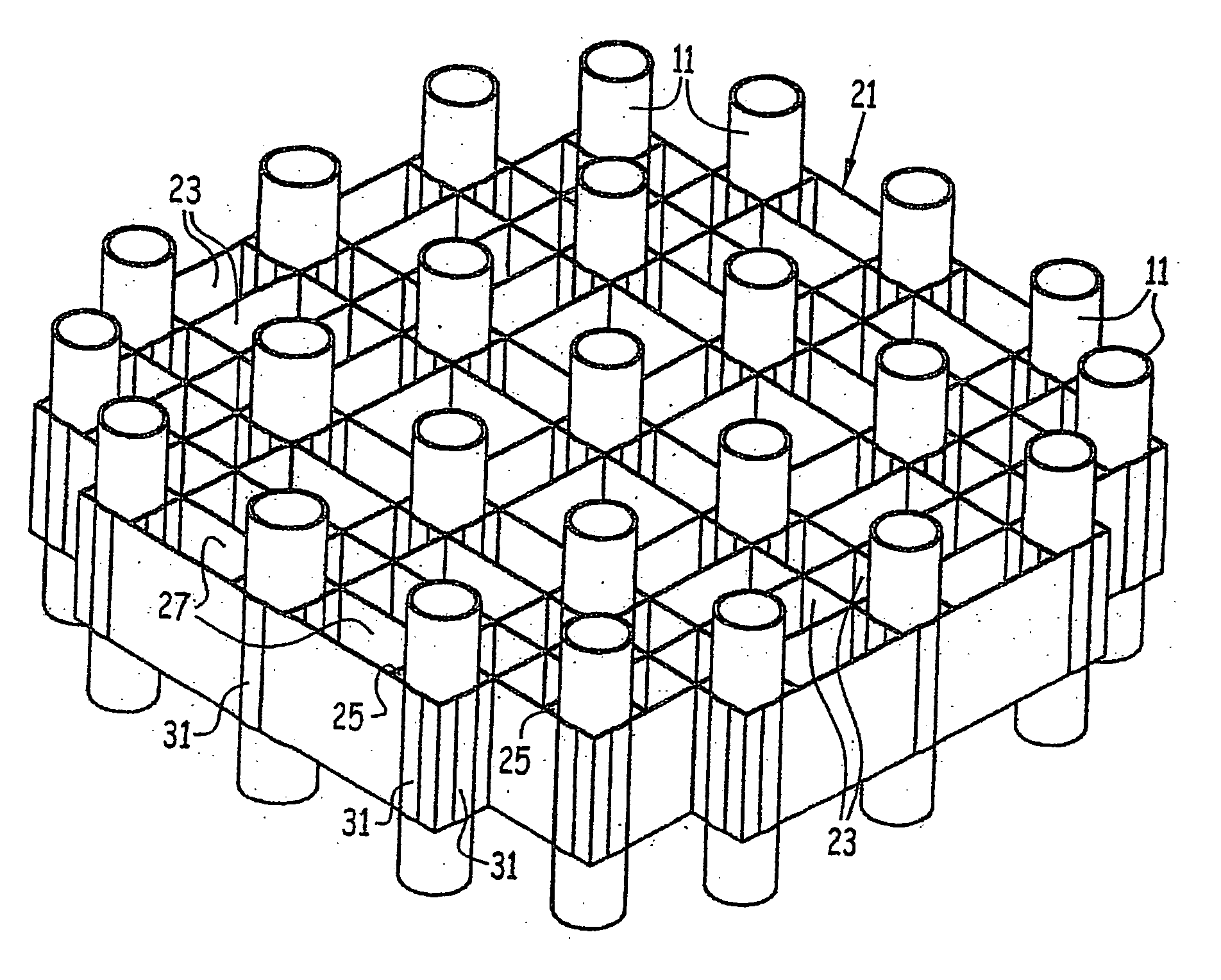
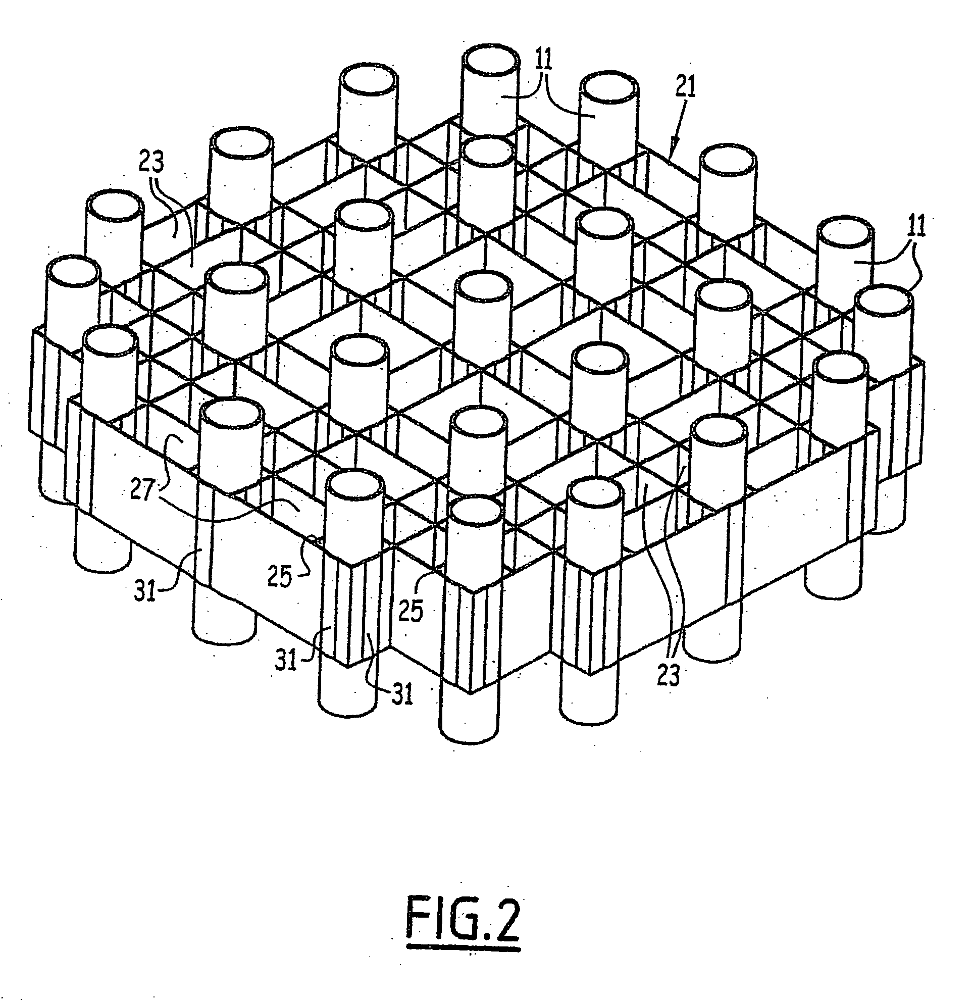
  • Nuclear fuel assembly comprising a reinforcing mesh device and the use of one such device in a nuclear fuel assembly
  • Nuclear fuel assembly comprising a reinforcing mesh device and the use of one such device in a nuclear fuel assembly
  • Nuclear fuel assembly comprising a reinforcing mesh device and the use of one such device in a nuclear fuel assembly

Examples


Embodiment Construction

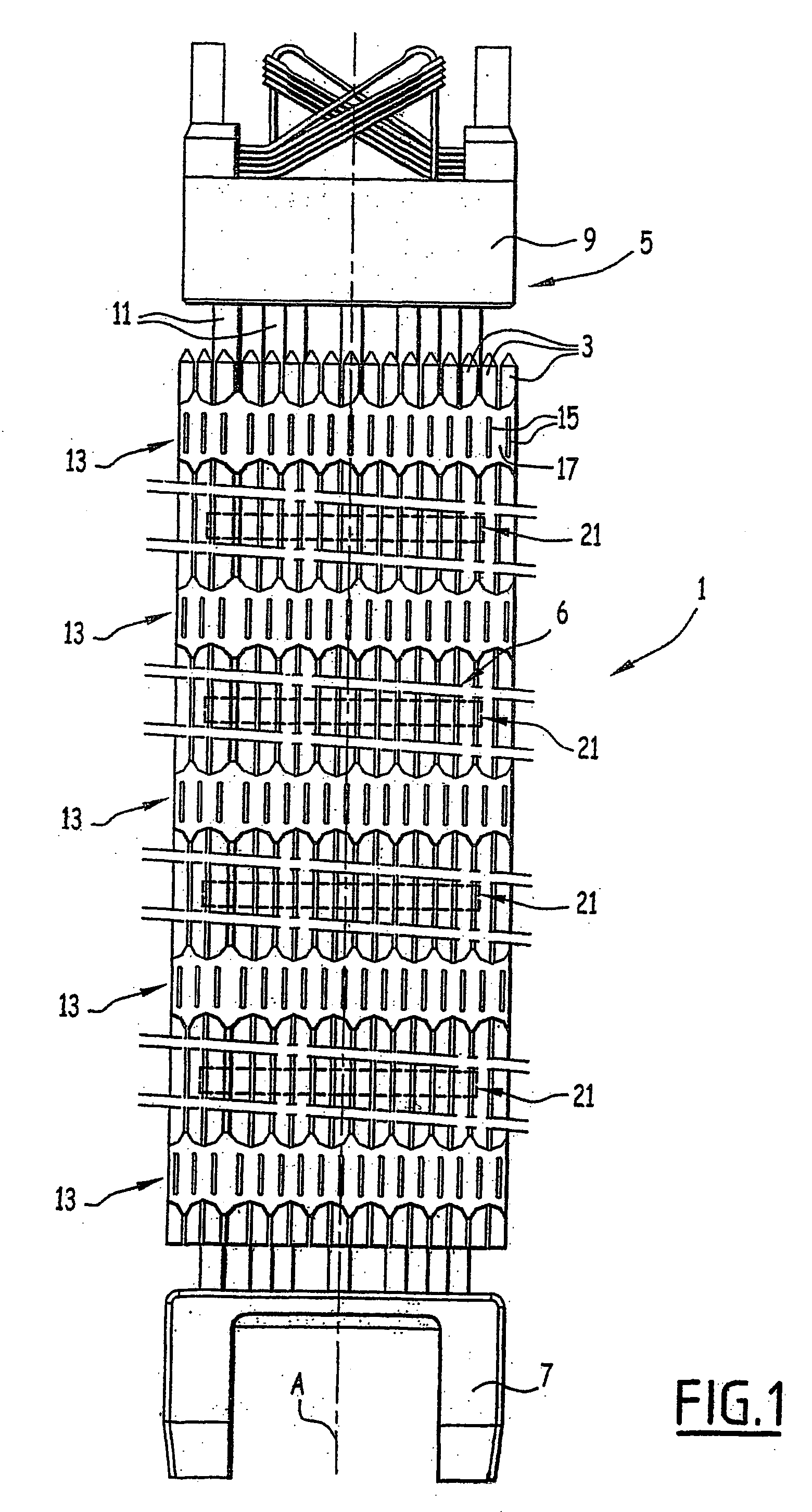
[0037]FIG. 1 is a diagram of a nuclear fuel assembly 1 for a pressurized water reactor. The assembly 1 extends vertically and in rectilinear manner along a longitudinal direction A.

[0038] The assembly 1 mainly comprises nuclear fuel rods 3 and a structure or skeleton 5 for supporting the rods 3.

[0039] In conventional manner, the rods 3 extend vertically and are disposed in a substantially regular, square-based array, as can be seen in FIG. 3 where the rods 3 are shown in dashed lines.

[0040] In the example shown, the assembly 1 comprises a group of 264 rods 3 and, seen from above, the array forms a square having a side of 17 rods. The group of rods 3 thus possesses four side faces 6 each having 17 rods.

[0041] The supporting skeleton 5 essentially comprises: [0042] a bottom nozzle 7 and a top nozzle 9; [0043] guide tubes 11 for receiving the rods of a control or shutdown cluster; and [0044] spacer grids 13 for holding the rods 3 at the nodes of the array.

[0045] The nozzles 7 and ...


PUM


Abstract

The nuclear fuel assembly having nuclear fuel rods and a support skeleton having two nozzles, guide tubes interconnecting the nozzles, and spacer grids for holding the rods, the grids being secured to the guide tubes. The assembly further has at least one lattice reinforcing device for reinforcing the support skeleton. The reinforcing device is placed between two spacer grids and is secured to the guide tubes. The invention is applicable to fuel assemblies for pressurized water reactors.

Description

FIELD OF THE INVENTION [0001] The present invention relates to nuclear fuel assemblies. By way of example, it applies to fuel assemblies for pressurized water nuclear reactors. BACKGROUND OF THE INVENTION [0002] Generally, nuclear fuel assemblies comprise nuclear fuel rods and a support skeleton having two nozzles, guide tubes interconnecting the nozzles, and spacer grids for holding the rods. [0003] Each spacer grid comprises two sets of crossed plates and an outer belt, thus defining cells, some of which have guide tubes passing through them and others have fuel rods passing through them. The plates are provided with means for holding the rods at the nodes of a substantially regular array and they are secured to at least some of the guide tubes. [0004] At least one of the spacer grids also serves to support the rods. For this purpose, it is usually provided with springs that are cut out in the plates or that are fitted to the plates, and that serve to press the rods against dimple...

Claims


Application Information

Patent Timeline
Patent Type & Authority Applications(United States)
IPC IPC(8): G21C3/34G21C3/32
CPCG21C3/32G21Y2002/104G21Y2002/303G21Y2004/304Y02E30/40Y02E30/30
Inventor BEATI, ANGELOMULLER, THIERRYRONDEMERRE, JEAN-FRANCOIS
Owner AREVA NP SAS
Why Eureka
Try Eureka