Separator tool for a modular prosthesis

a modular prosthesis and tool technology, applied in the field of modular orthopaedic prosthesis, can solve the problems of inability to use a one-piece prosthesis, inability to use a bone chisel to wedge fixed components apart, and inability to use a bone chisel to wedge fixed components, etc., to achieve the effect of increasing the gap between modular components

Active Publication Date: 2007-04-05
DEPUY PROD INC
View PDF43 Cites 71 Cited by
  • Summary
  • Abstract
  • Description
  • Claims
  • Application Information

AI Technical Summary

Benefits of technology

[0013] In order to address this need, a tool is provided that permits separation of fixed components of a modular prosthesis without the need for use of a bone chisel and an impaction tool. The tool of one embodiment of the invention allows for the application of uniform pressure against both the sleeve and the component to be removed to gradually increase the gap between the modular components. The tool may be used in virtually any orientation without requiring undue manipulation of the patient's joint.
[0018] It is one object of the invention to provide a tool that is operable to separate components of a modular prosthesis in situ. A further object of the invention is achieved by features that allow this separation to occur without compromising the integrity of components that are intended to remain within the bone or joint.

Problems solved by technology

Such a need for prostheses of varying shapes and sizes created a number of problems in regard to use of a one-piece prosthesis.
At any rate, the otherwise beneficial self-locking characteristics of the modular prostheses 10 / 10′ become a disadvantage in a revision procedure where it is necessary to separate the neck and stem components from the stable well-fixed sleeve.
This technique suffers from a few problems.
Foremost is the inherent difficulties associated with using a bone chisel to wedge fixed components apart.
The chisel may slip out of place and damage surrounding tissue or cut through the surgeon's gloves.
In addition, the use of an impaction tool to separate the components from the sleeve tends to produce an axial load on the sleeve that can tend to disassociate the sleeve from the proximal end of the femur.

Method used


Image

  • Separator tool for a modular prosthesis
  • Separator tool for a modular prosthesis
  • Separator tool for a modular prosthesis

Examples


Embodiment Construction

[0028] For the purposes of promoting an understanding of the principles of the invention, reference will now be made to the embodiments illustrated in the drawings and described in the following written specification. It is understood that no limitation to the scope of the invention is thereby intended. It is further understood that the present invention includes any alterations and modifications to the illustrated embodiments and includes further applications of the principles of the invention as would normally occur to one skilled in the art to which this invention pertains.

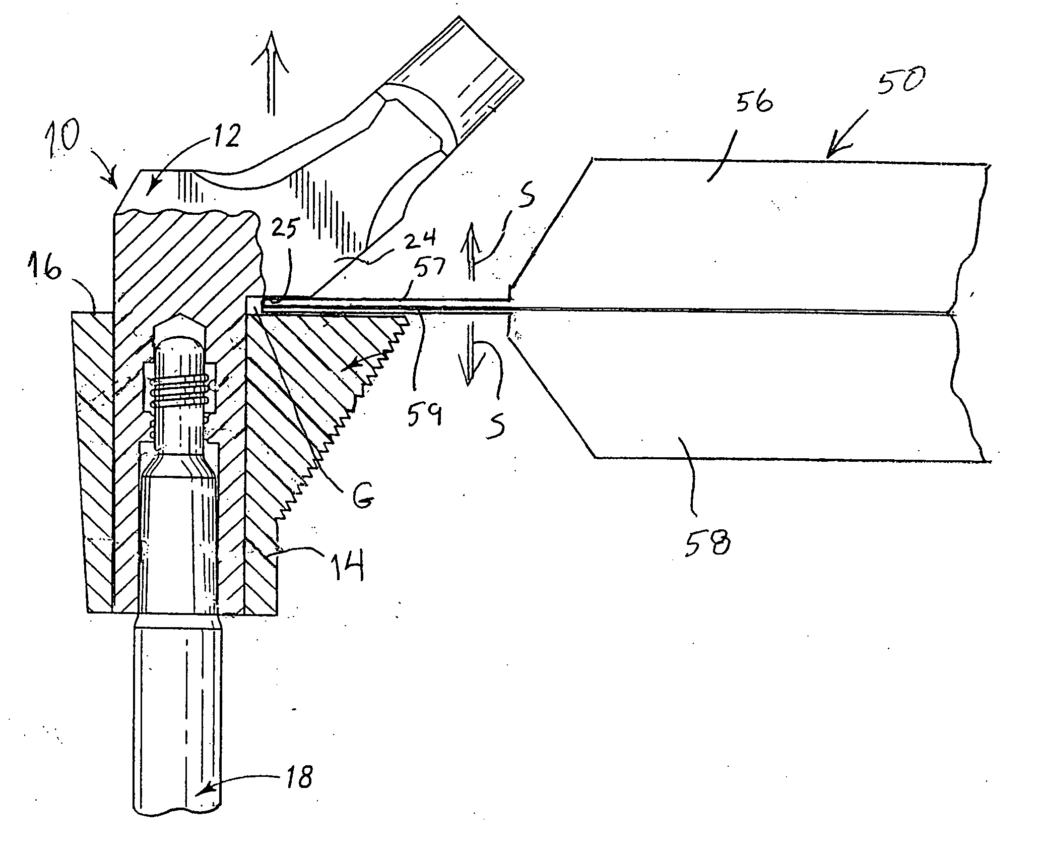
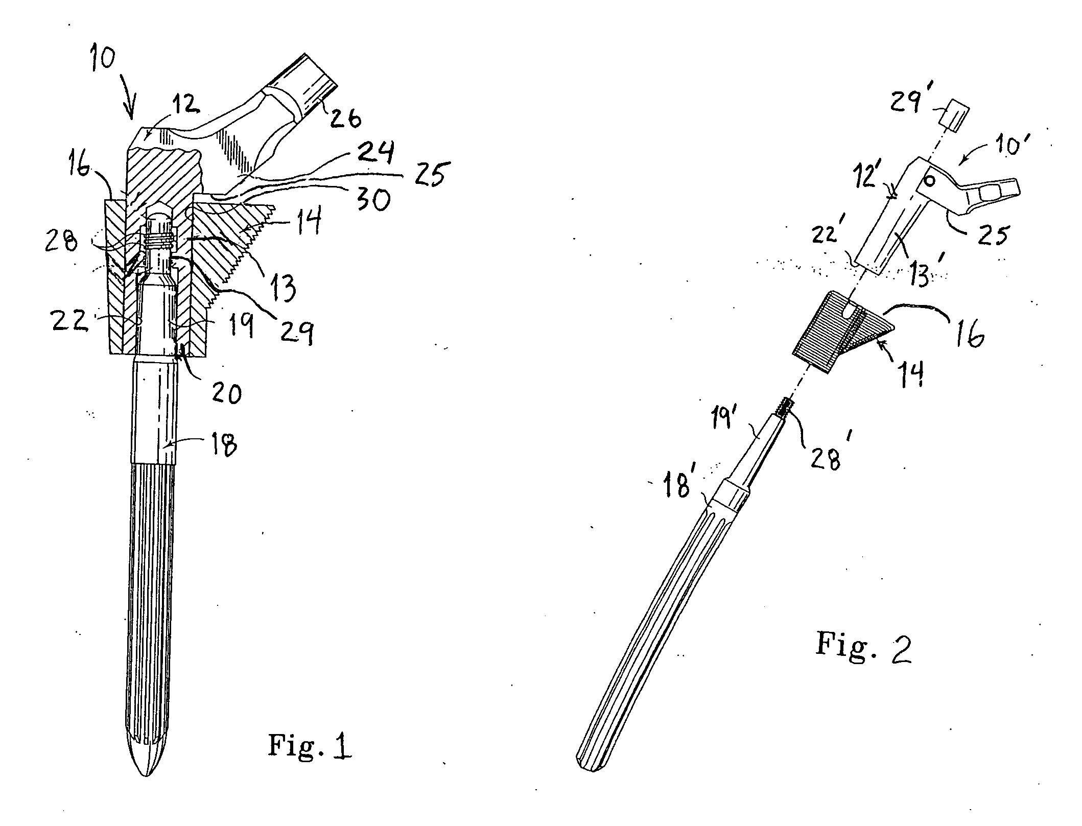
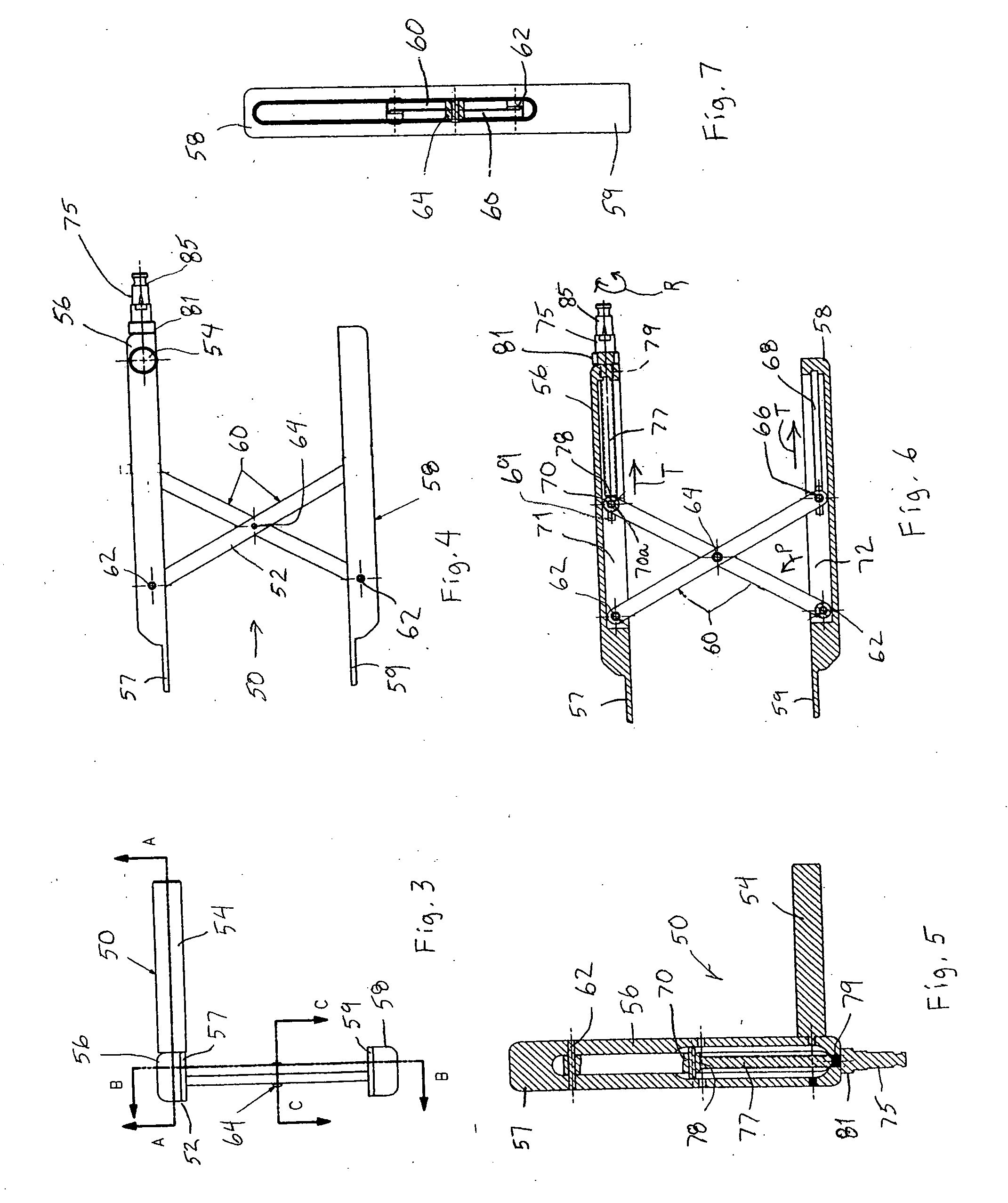
[0029] In accordance with one embodiment of the invention, a separation tool 50 is provided that includes a pair of separator bodies 56, 58 connected by and separable by a jack assembly 52, as shown in FIGS. 3-6. The jack assembly 52 is operable to move the upper body 56 and the lower body 58 between an expended position depicted in FIG. 4 and a contracted, or insertion, position shown in FIG. 8. The upper bod...


PUM


Abstract

A tool for separating components of a modular prosthesis includes an upper and lower body, each defining opposing bills at one end that are sized to fit in juxtaposed relation within an initial gap between the components. The upper body is provided with a handle so that the tool may be manually held by the surgeon with the opposing bills in position in the prosthesis. The tool includes a jack assembly disposed between the upper and lower bodies of the tool that is configured to be driven into an extended position, gradually separating the upper and lower bodies, and consequently exerting a separation force on the prosthesis components through the bills of the tool. The jack assembly is driven by a threaded actuator rod that bears against one element of the jack assembly as the actuator rod is rotated within a threaded bore in one of the bodies of the tool.

Description

TECHNICAL FIELD OF THE INVENTION [0001] The present invention relates generally to modular orthopaedic prostheses, and more particularly to a tool for separating components of a modular prosthesis in situ. BACKGROUND OF THE INVENTION [0002] During the lifetime of a patient, it may be necessary to perform a joint replacement procedure to address damage to the joint due to, for example, disease or trauma. The joint replacement procedure may involve the use of a prosthesis which is implanted into at least one of the patient's bones. In the case of a hip replacement procedure, a femoral prosthesis is implanted into the patient's thigh bone or femur. The femoral prosthesis had been typically constructed as a one-piece structure having an upper portion that includes a spherically-shaped head which bears against the patient's pelvis or acetabulum, along with an elongated intramedullary stem which is utilized to secure the femoral component to the femur. In order to secure this prosthesis t...

Claims


Application Information

Patent Timeline
Patent Type & Authority Applications(United States)
IPC IPC(8): A61F2/46A61B17/92
CPCA61F2/36A61F2/4637A61F2002/30525A61F2002/4641A61F2002/469A61F2002/4694A61F2220/0025
Inventor JONES, MICHAEL C.DEBOER, DAVID K.
Owner DEPUY PROD INC
Why Eureka
Try Eureka