
Process model identification in a process control system

a technology of process control system and process model, applied in the field of process control system identification and application of process model in can solve the problems of increasing the complexity of the process control system, limited use of adaptive control techniques in the process industry, and difficulty in determining which process control loops

Active Publication Date: 2007-04-05
FISHER-ROSEMOUNT SYST INC
View PDF4 Cites 70 Cited by
  • Summary
  • Abstract
  • Description
  • Claims
  • Application Information

AI Technical Summary

Benefits of technology

[0017] The method may also include identifying respective process models for each control routine of the plurality of control routines. The plurality of control routines may include a control routine that implements a non-adaptive control scheme.

Problems solved by technology

The introduction of multiple process models and the requisite automatic generation of the controller to matching the current process condition undesirably increased the complexity of the process control system.
Despite the promise of improved control performance, the use of adaptive control techniques in the process industries has been limited, insofar as the techniques have often been difficult to implement in practice.
Unfortunately,.it is often difficult to determine which process control loops would benefit from the implementation of adaptive control, i.e., which loops should be selected for adaptive control capability.
But regardless of the size or complexity of the plant, conventional process control systems typically do not support the creation of process models for all of the control loops in the plant.
Making matters worse, the manual testing necessary to identify new process models for all the control loops may not be practicably performed.
In operation, the adaptive control techniques have provided limited diagnostic capabilities.
As a result, the process control system may fail to provide an indication of an abnormal condition in the process or instrumentation that is causing control performance to suffer.

Method used


Image

  • Process model identification in a process control system
  • Process model identification in a process control system
  • Process model identification in a process control system

Examples


Embodiment Construction

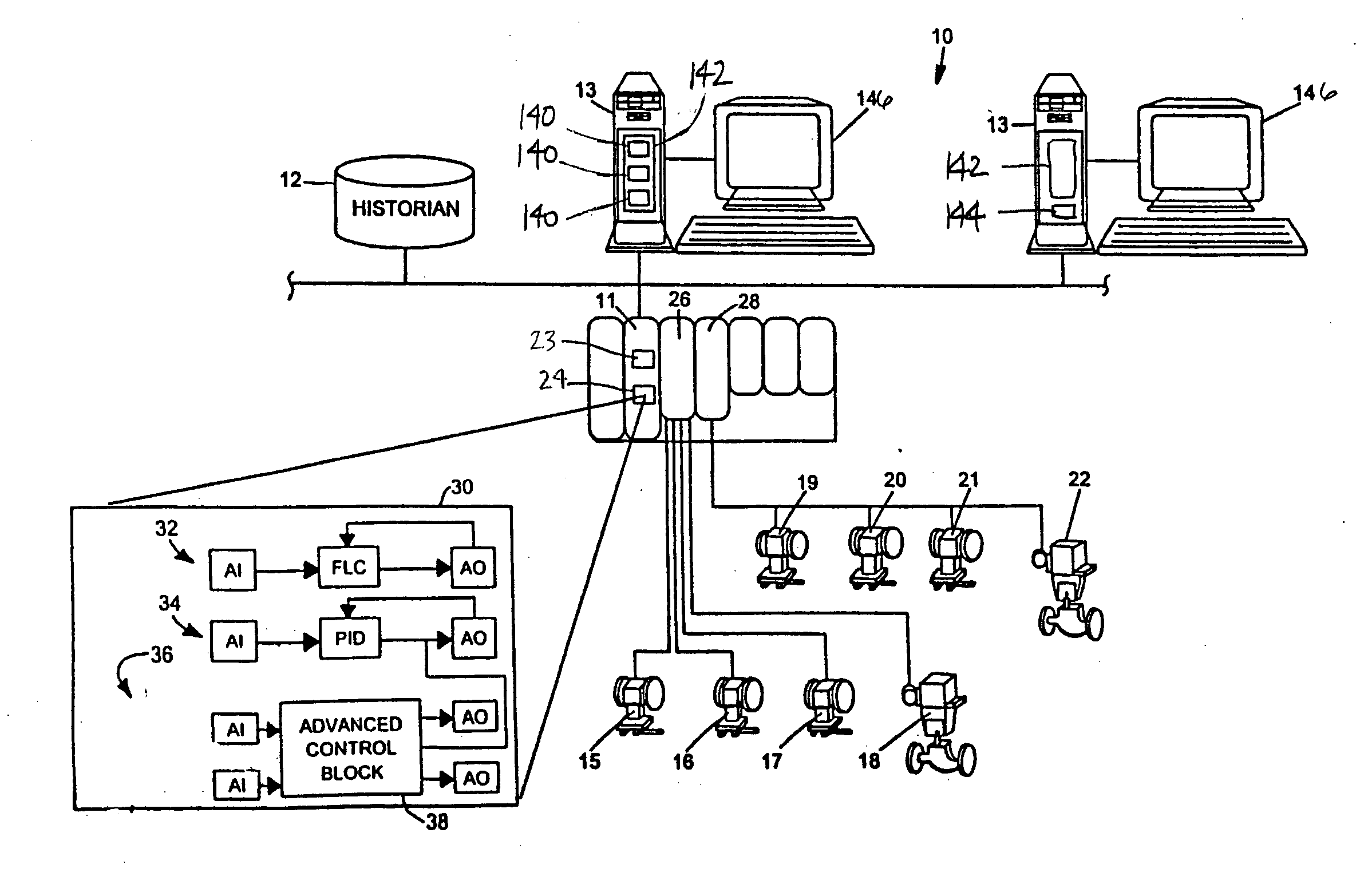
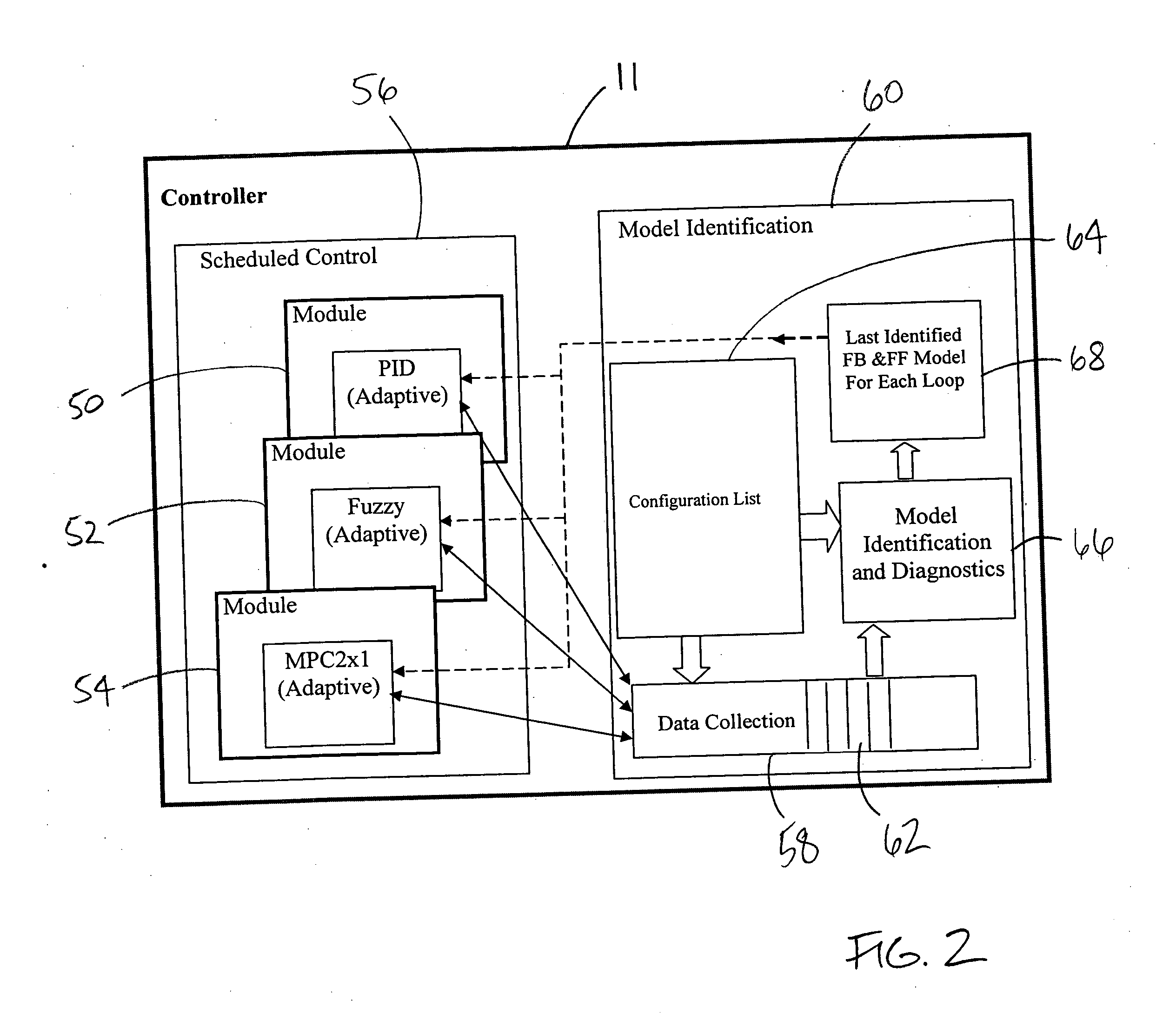
[0035] Disclosed herein are a process control system and method that implement a technique that automatically identifies process models for control loops in the process control system that are not necessarily currently utilizing a process model for adaptive control. The process models are created, therefore, for reasons other than (or in addition to) the implementation of adaptive control. For instance, the decision as to which control loops should have adaptive control applied thereto is made easier via evaluation of the process models identified via the disclosed technique.

[0036] In some cases, the identification of process models is extended to all control loops in the process control system. In this way, process models may be generated for every node of the process control system. But regardless of whether process models are being identified for every control loop or node in specific embodiments of the disclosed system, the extension of process model identification to non-adapt...


PUM


Abstract

Disclosed is a method of controlling and managing a process control system having a plurality of control loops. The method includes implementing a plurality of control routines to control operation of the plurality of control loops, respectively. The plurality of control routines may include at least one non-adaptive control routine. Operating condition data is then collected in connection with the operation of each control loop of the plurality of control loops, and a respective process model is identified for each control loop of the plurality of control loops from the respective operating condition data collected for each control loop of the plurality of control loops. In some embodiments, the identification of the respective process models may be automatic as a result of a detected process change or be on-demand as a result of an injected parameter change.

Description

TECHNICAL FIELD [0001] The present invention relates generally to process control systems and, more particularly, to the identification and application of process models in process control systems. DESCRIPTION OF THE RELATED ART [0002] Process control systems, such as distributed or scalable process control systems like those used in chemical, petroleum or other processes, typically include one or more process controllers communicatively coupled to each other, to at least one host or operator workstation and to one or more field devices via analog, digital or combined analog / digital buses. The field devices, which may be, for example, valves, valve positioners, switches and transmitters (e.g., temperature, pressure and flow rate sensors), perform functions within the process such as opening or closing valves and measuring process parameters. The process controller receives signals indicative of process measurements made by the field devices and / or other of information pertaining to ...

Claims


Application Information

Patent Timeline
Patent Type & Authority Applications(United States)
IPC IPC(8): G05B13/02
CPCG05B13/048G05B23/0254G05B23/0272G05B13/04G05B19/0428
Inventor CALDWELL, JOHNBLEVINS, TERRENCE L.WOJSZNIS, PETERWOJSZNIS, WILHELM K.
Owner FISHER-ROSEMOUNT SYST INC
Learn More