Supercharge Your Innovation With Domain-Expert AI Agents!

Cyclic redundancy check circuit and communication system having the same for multi-channel communication

a communication system and circuit technology, applied in the field of cyclic redundancy check circuits and communication systems having the same in multi-channel serial communication systems, can solve problems such as a different cr

Active Publication Date: 2007-04-05
SAMSUNG ELECTRONICS CO LTD
View PDF10 Cites 5 Cited by
  • Summary
  • Abstract
  • Description
  • Claims
  • Application Information

AI Technical Summary

Benefits of technology

[0025] While the conventional CRC circuit includes only r modulo-2 adders (corresponding to the r bits of the CRC, where r is up to or equal to, but

Problems solved by technology

If an error has occurred, there will probably be a different CRC result.

Method used


Image

  • Cyclic redundancy check circuit and communication system having the same for multi-channel communication
  • Cyclic redundancy check circuit and communication system having the same for multi-channel communication
  • Cyclic redundancy check circuit and communication system having the same for multi-channel communication

Examples


Embodiment Construction

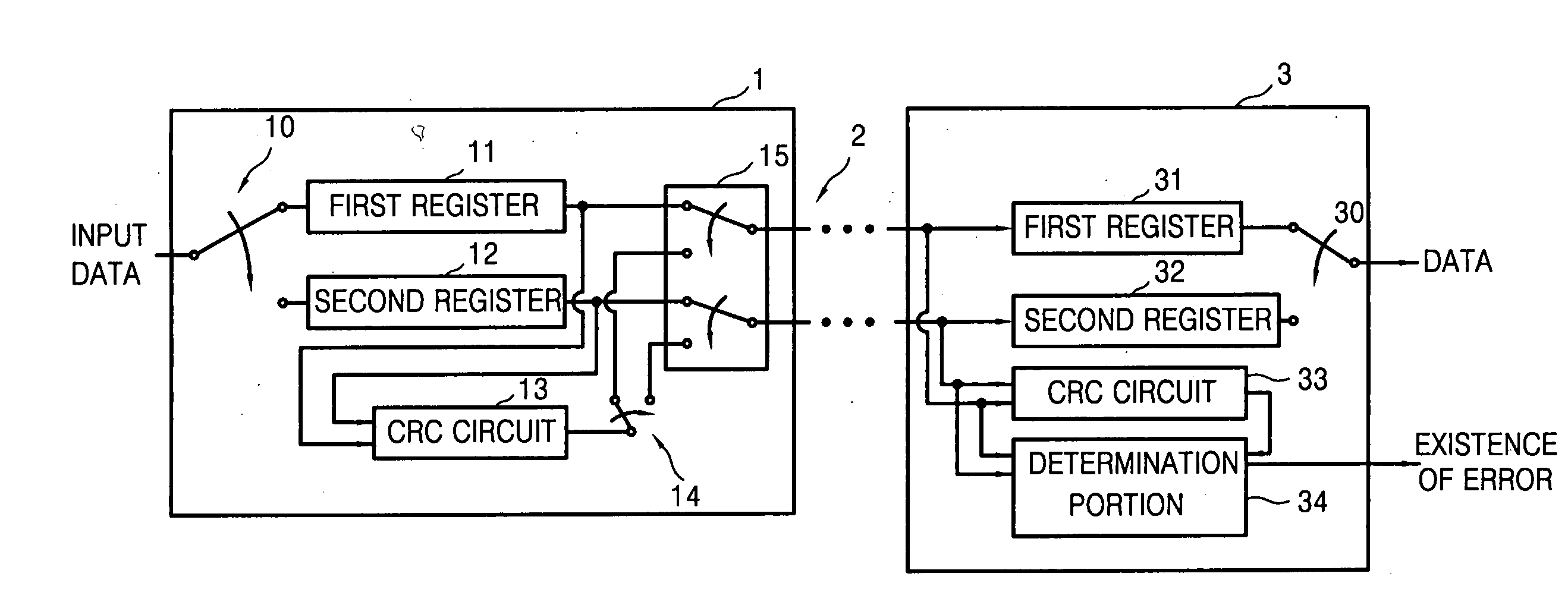
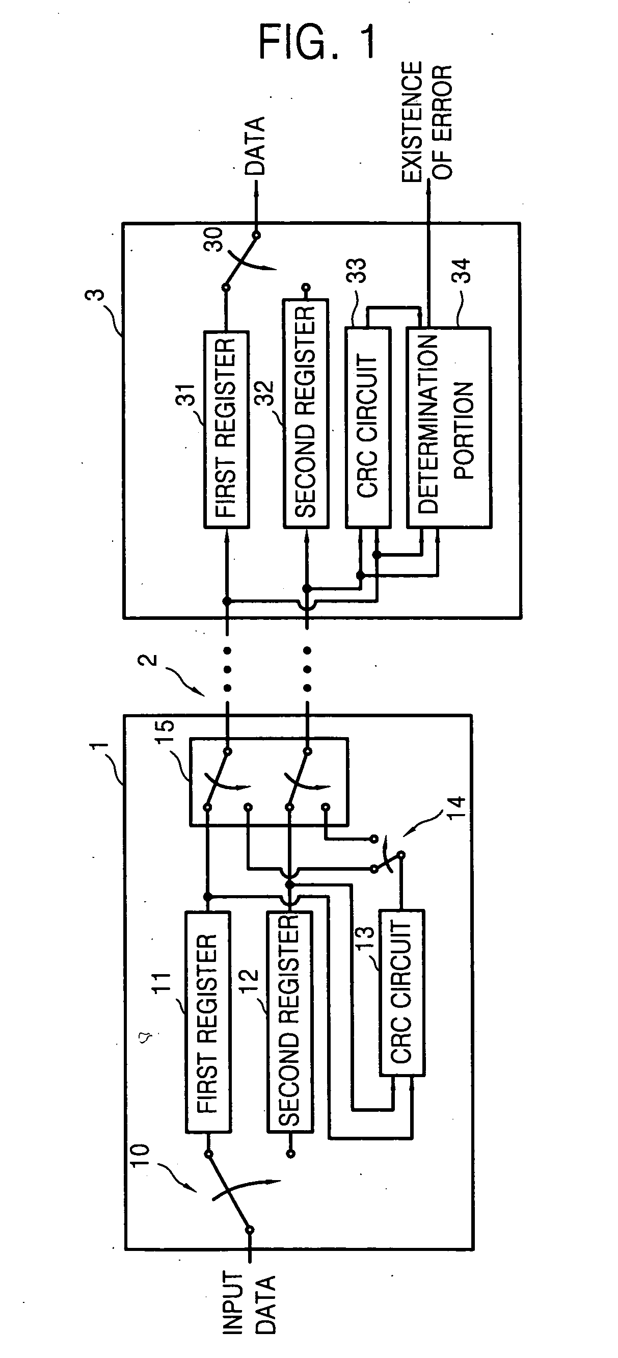
[0035]FIG. 1 is a block diagram of a communication system that communicates (transmits and receives) through a multi-channel (through multiples channels) including a cyclic redundancy check circuit according to an embodiment of the present invention. The system of FIG. 1 includes a transmission circuit (transmitter) 1 and a receiving circuit (receiver) 3. The transmission circuit 1 transmits data to a receiving circuit 3 through a multi-channel 2. Although the multi-channel 2 has only two channels (for the convenience of simpler explanation), the present invention is not limited thereto and can be extended to any multiple number of channels.

[0036] The transmission circuit 1 includes a first register 11, a second register 12, a cyclic redundancy check (CRC) circuit 13, a switch 14, and a switching portion (multiplexer) 15. The transmission circuit 1 may further include a switch 10 to convert input serial data to parallel data. For the convenience of explanation, the switch 10 and th...


PUM


Abstract

A method of implementing and manufacturing a cyclic redundancy check circuit for a multi-channel communication system. The method includes creating a generation expression that generates cyclic redundancy check (CRC) bits that satisfies a cyclic redundancy check polynomial of a mono-channel serial communication system with respect to a first point in time, creating a generation expression with respect to points in time that are sequentially delayed as much as the number of multi-channels from the first point in time by applying each point in time to the generation expression, and embodying a circuit corresponding to the generation expression with respect to the most delayed point in time among the created generation expressions. The CRC circuit corresponding to the generation expression will have more modulo-2 adders (e.g., XOR gates) than the number of non-zero coefficients in the selected CRC polynomial.

Description

CROSS-REFERENCE TO RELATED PATENT APPLICATIONS [0001] This application claims the priority, under 35 U.S.C. § 119, of Korean Patent Application No. 10-2005-0084550, filed on Sep. 12, 2005, in the Korean Intellectual Property Office, which is incorporated herein in its entirety by reference. BACKGROUND OF THE INVENTION [0002] 1. Field of the Invention [0003] The present invention relates to a cyclic redundancy check (CRC) circuit and a communication system having the same, and more particularly, to a cyclic redundancy check (CRC) circuit and a communication system having the same in a multi-channel serial communication system such as a high definition multimedia interface (HDMI). [0004] 2. Description of the Related Art [0005] HDMI is a cable and interface for transmitting uncompressed digital audio and video data between an audio / video source such as a set-top box (e.g., a cable box, of a satellite receiver) or a DVD player and a display such as a digital TV. HDMI supports standard ...

Claims


Application Information

Patent Timeline
IPC IPC(8): H03M13/00H04N19/89H04N21/438
CPCH03M13/091H04L1/0041H04L1/0045H04N19/21H04L25/14H04N19/42H04N19/20H04L1/0061H04L1/004H04L1/22
Inventor KWAK, JAE-YOUNG
Owner SAMSUNG ELECTRONICS CO LTD
Features
  • R&D
  • Intellectual Property
  • Life Sciences
  • Materials
  • Tech Scout
  • Unparalleled Data Quality
  • Higher Quality Content
  • 60% Fewer Hallucinations
Learn More