Sawing angle indicating-and-reading device for a table sawing machine

Inactive Publication Date: 2007-04-12
CHUANG BOR YANN
View PDF8 Cites 0 Cited by
  • Summary
  • Abstract
  • Description
  • Claims
  • Application Information

AI Technical Summary

Benefits of technology

[0006] The objective of the invention is to offer a sawing angle indicating-and-reading device for a table sawing machine, which is provided with an angular signal reading head, an angle sensing device and a circuit device. The angular signal reading head is firmly fitted with the inner end of a driving connecting rod to rotate together with the driving connecting rod for producing a signal and putting it out to the circuit device. By this signal, the increase or decrease in an angle of the angular signal reading head can be read, and the turned angle of the saw base can be accurately indicated on a digital indicator, able to elevate precision in sawing.

Problems solved by technology

However, the angle indicating dial 3 of the conventional table sawing machine indicates the turning angles of the saw base 1 in an analog graduated way; therefore, it is hard to accurately indicate the turned angle of the saw base, thus affecting precision in sawing.

Method used


Image

  • Sawing angle indicating-and-reading device for a table sawing machine
  • Sawing angle indicating-and-reading device for a table sawing machine
  • Sawing angle indicating-and-reading device for a table sawing machine

Examples


Embodiment Construction

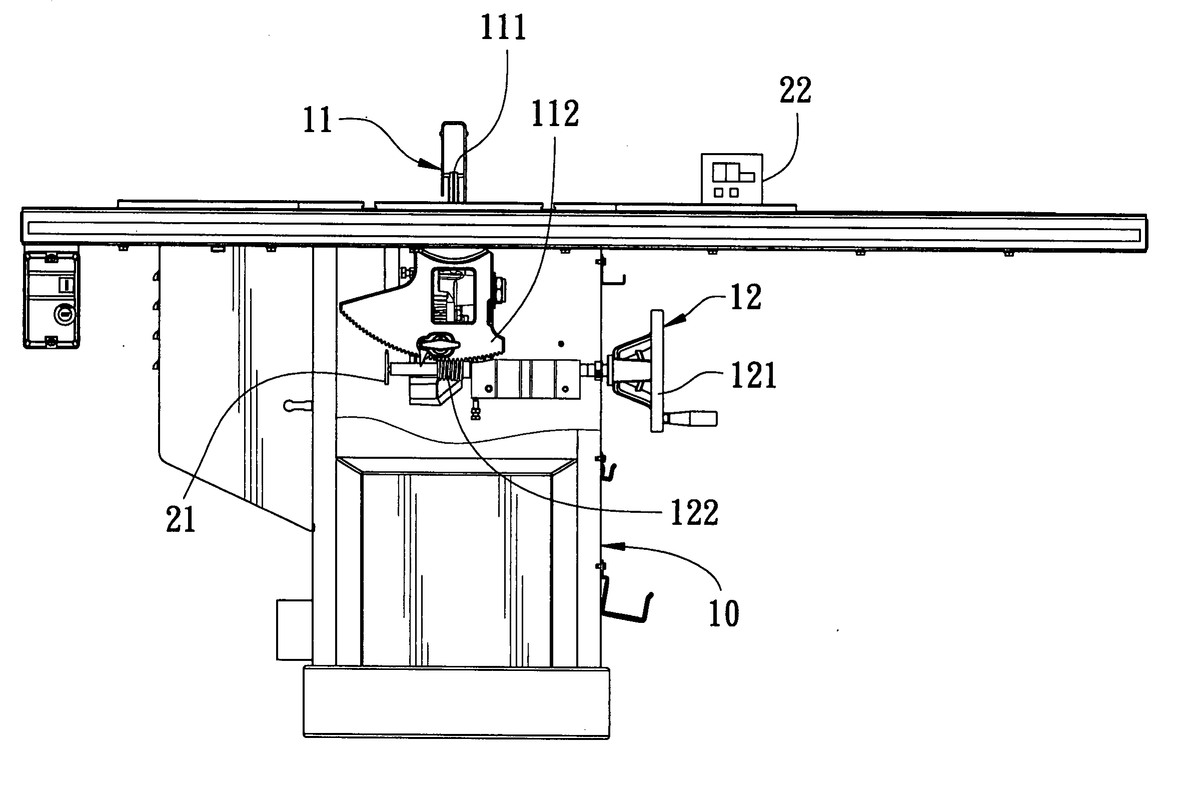
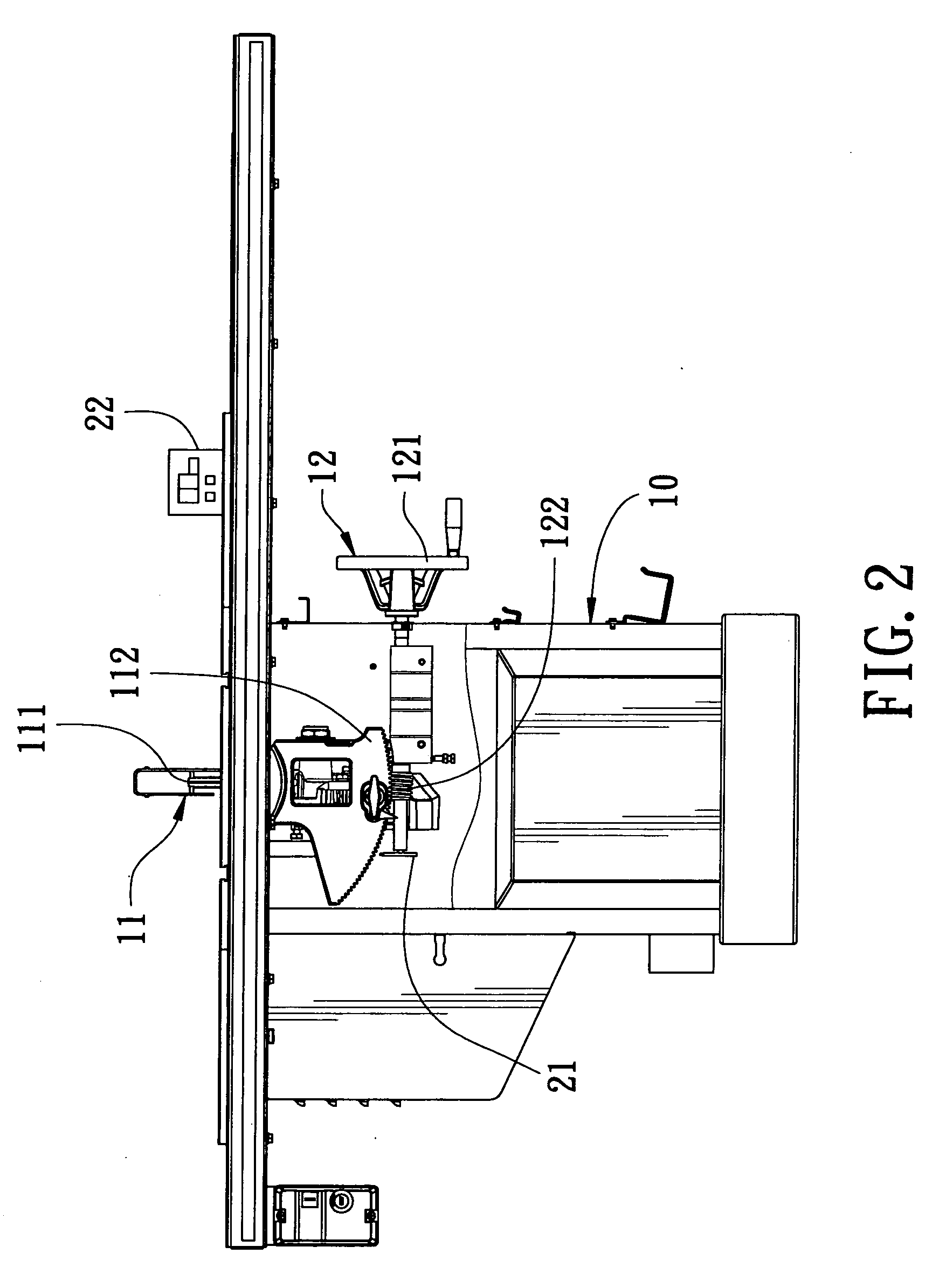
[0013] A preferred embodiment of a sawing angle indicating- and-reading device for a table sawing machine in the present invention, as shown in FIGS. 2, 3 and 4, includes a machine body 10, a saw base 11, a driving connecting rod 12 and an angle sensing device 20 combined together.

[0014] The machine body 10 is assembled thereon with the saw base 11 and the driving connecting rod 12.

[0015] The saw base 11 is mainly composed of a saw blade 111 and a sector gear 112. The saw blade 111 is actuated by the sector gear 112 to shift bias for an angle and carry out sawing.

[0016] The driving connecting rod 12 has its outer end connected with a hand-wheel 121 and its inner end fixed with a worm 122 engaging with the sector gear 112 of the saw base 11. The hand-wheel 121 can be freely turned for any angle for actuating the driving connecting rod 12 and the worm 122 to rotate and drive the sector gear 112 to shift bias for an angle.

[0017] The angle sensing device 20 consists of an angular si...


PUM

PropertyMeasurementUnit
Angleaaaaaaaaaa

Abstract

A sawing angle indicating-and-reading device for a table sawing machine includes a saw base, a driving connecting rod and an angle sensing device. The driving connecting rod is actuated to drive the saw base to shift bias for an angle. The angle sensing device is composed of an angular signal reading head and a circuit device. The angular signal reading head is firmly fitted on the inner end of the driving connecting rod to rotate together with the driving connecting rod for producing an angle increasing or decreasing signal and putting it out to the circuit device and simultaneously, the circuit device will put out a digital angular value. By so designing, the sawing angles of the table sawing machine can easily and accurately be read, able to elevate precision in sawing.

Description

BACKGROUND OF THE INVENTION [0001] 1. Field of the Invention [0002] This invention relates to a sawing angle indicating-and-reading device for a table sawing machine, particularly to one able to accurately measure and indicate the deflecting angle of the saw base of a table sawing machine and re-correct the measured angular value. [0003] 2. Description of the Prior Art [0004] A conventional table sawing machine, as shown in FIG. 1, includes a saw base 1, a driving connecting rod 2 and an angle indicating dial 3 installed at a preset location on the table sawing machine. The driving connecting rod 2 is actuated to drive the saw base 1 to shift bias for an angle, and the angle indicating dial 3 indicates a turned angle of the saw base 1. [0005] However, the angle indicating dial 3 of the conventional table sawing machine indicates the turning angles of the saw base 1 in an analog graduated way; therefore, it is hard to accurately indicate the turned angle of the saw base, thus affecti...

Claims


Application Information

Patent Timeline
IPC IPC(8): B26D7/27
CPCB23D59/002Y10T83/773Y10T83/849Y10T83/853
Inventor CHUANG, BOR-YANN
Owner CHUANG BOR YANN
Why Eureka
Try Eureka