Fuel composition sensing systems and methods using EMF wave propagation

Active Publication Date: 2008-07-03
SCHRADER ELECTRONICS LTD
View PDF13 Cites 5 Cited by
  • Summary
  • Abstract
  • Description
  • Claims
  • Application Information

AI Technical Summary

Benefits of technology

[0011]In particular, embodiments of the present invention may be used in FFVs to detect the percentage of ethanol content in the fuel. This information can be constantly reported to the EMS or Body Control Module of the FFV, allowing the EMS to respond accordingly, thereby promoting performance, efficiency and / or the like. Advantageously the present invention provides immediate accurate ethanol content information without any direct contact with fuel, minimizing emissions, risk of fuel leak, risk of major car breakdown failure, and / or the like.
[0017]In accordance with some embodiments of the present invention a signal of a constant frequency may be generated across a resonant circuit, which comprises an inductor and a PCB trace capacitor, capacitor plates, or the like. Electromagnetic radiation may be propagated into the fuel, such as the passing fuel in a fuel transfer pipe. The conductivity and dielectric properties of the fuel may impact upon the electromagnetic field and may change the capacitance of the capacitor, the trace capacitor, the capacitor plates or other such capacitive device or devices which comprise the resonant circuit. Such changes may be proportional to the constituents of the fuel and may, for example be representative of the alcohol / ethanol content in the fuel. Such changes may be detected by a microcontroller, or the like, and may be communicated to a second microcontroller, to the EMS, to a device external to the flex fuel sensor, and / or other device. Such communications may be asynchronous or may be synchronized to an external device, and may be triggered by a signal from an external device, and / or the like As such the present invention provides a non-invasive, cost effective solution, well suited, not only for original equipment applications but also for up-fit or retro-fit or the like. The present systems and methods are highly responsive and provide immediate information to, an EMS or similar device, allowing quick and accurate adjustments to be made which may facilitate improvement and / or maintenance of vehicle performance.
[0020]The present systems and methods may employ auto-calibration hardware and software that enables a flex fuel sensor of the present invention to determine an optimum system operating frequency. In one embodiment of the present invention, the optimum system operating frequency is selected to be a frequency above or below the resonant frequency of the resonant LCR circuit. The choice of this operating frequency over the resonant frequency may allow for larger changes in voltage drop as impacted by changes in liquid composition. Preferably, the system of such embodiments is tuned to operate at a frequency between a lower and upper value.
[0022]By measuring fuel composition in-line, the present systems and methods may provide an EMS or other engine control device dynamic, accurate fuel composition information regardless of the fuel storage system employed and ongoing mixing of fuel in saddle tanks or similar storage arrangements.

Problems solved by technology

Algorithm-based systems are slow to react to changes in the fuel composition and are typically only accurate to plus or minus ten percent alcohol content.
Furthermore, such systems are even more ineffective when employed in a motor vehicle with saddle fuel tanks or similar fuel storage arrangements where the fuel may not be uniformly mixed or where the fuel mixture might change over time as the vehicle is driven.
Repair, replacement, or adjustment of such an internal or in-line fuel composition measurement mechanism is problematic.
The prior art fails to provide a reliable, inexpensive, and accurate system and method of measuring the composition of fuel in a motor vehicle using a system that can be installed external to a fuel line, fuel tank, or the like.
The loading effect of the fuel may cause a shift in the resonant frequency of the circuit and / or a change in the Q (quality factor) of the resonant circuit.

Method used


Image

  • Fuel composition sensing systems and methods using EMF wave propagation
  • Fuel composition sensing systems and methods using EMF wave propagation
  • Fuel composition sensing systems and methods using EMF wave propagation

Examples


Embodiment Construction

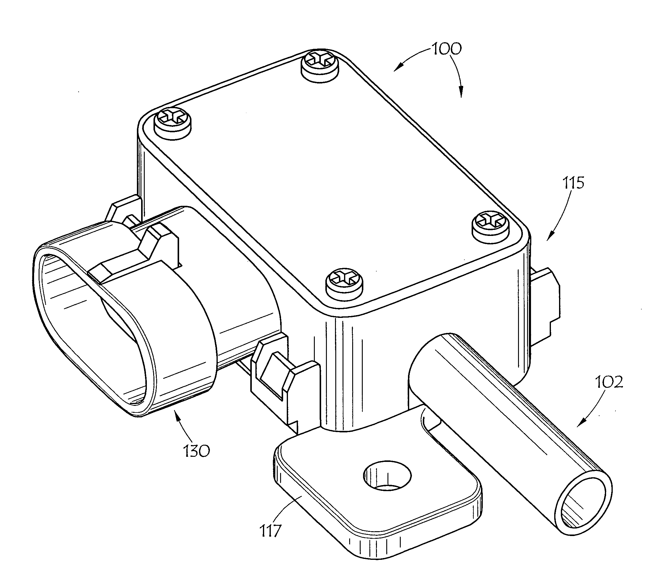
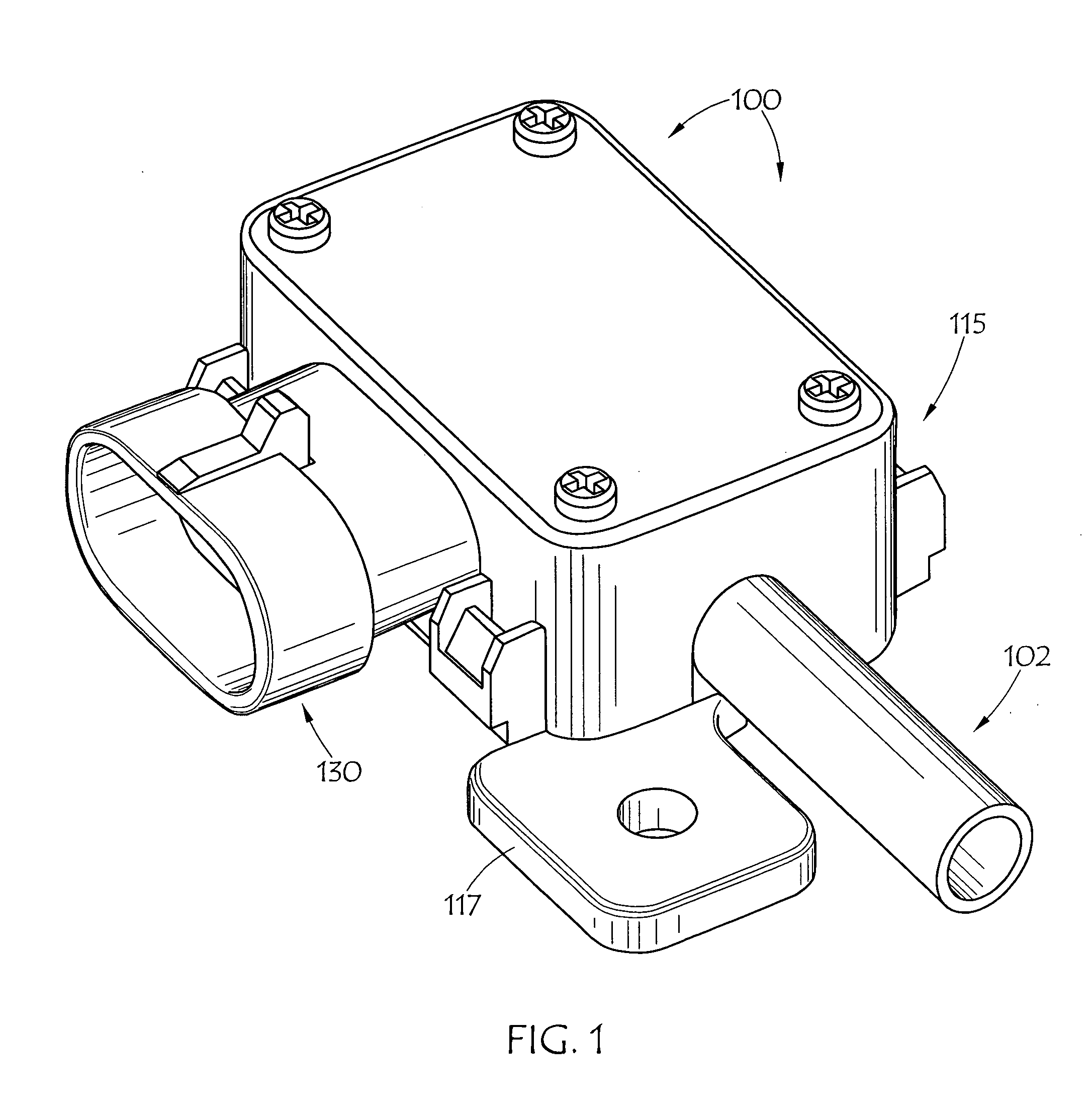
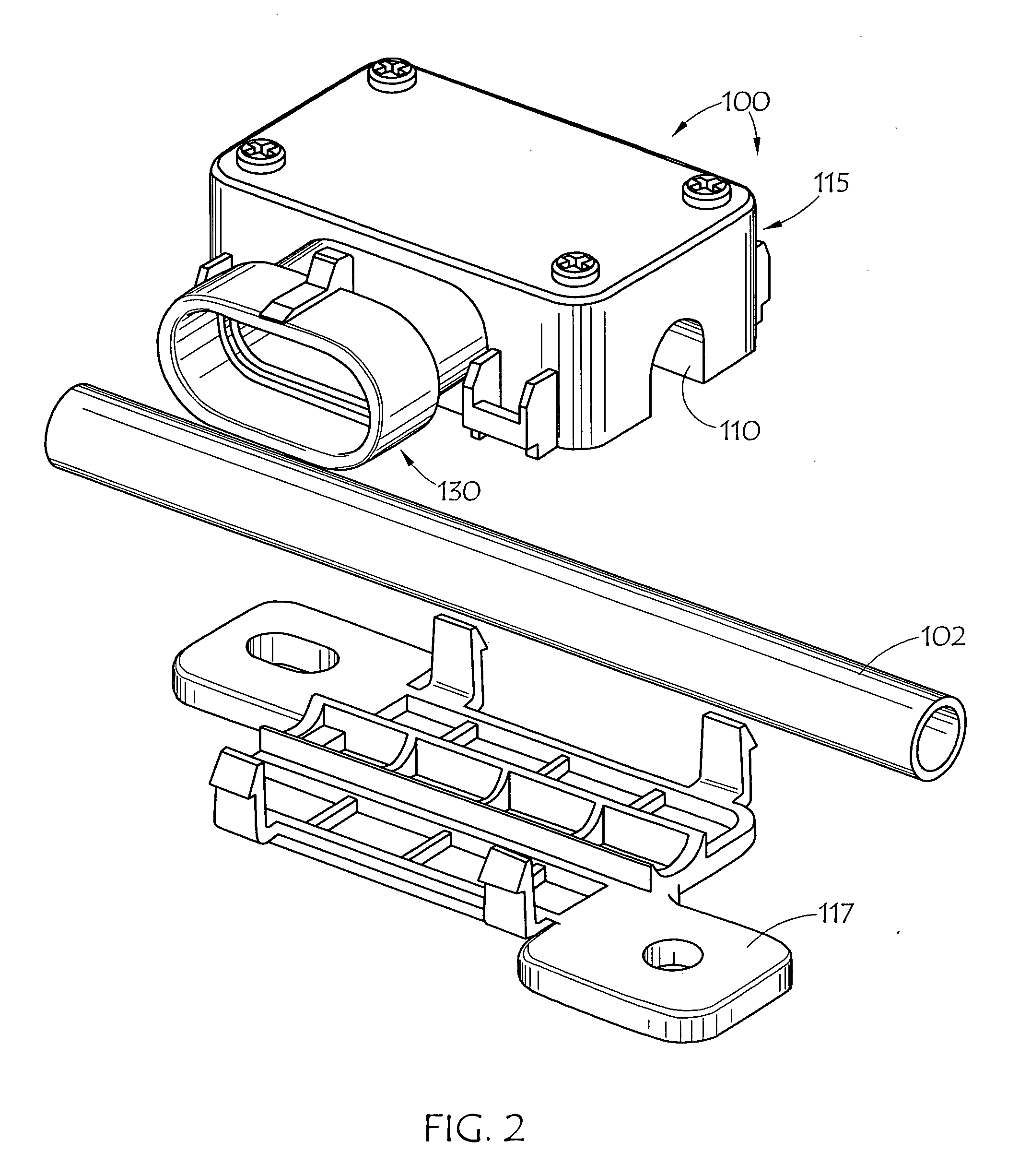
[0030]FIGS. 1 and 2 show an embodiment of flex fuel sensor 100 of the present invention disposed in conjunction with fuel line 102, such as mounting flex fuel sensor housing 115 to base plate 117, encompassing fuel line 102. Alternative embodiments call for mounting a flex fuel sensor of the present invention to the side or bottom of a fuel tank. Generally, fuel line 102 or the aforementioned fuel tank is comprised of a non-conductive material such as plastic.

[0031]FIG. 3 illustrates an embodiment of PCB 105 and capacitor plates 110 and 112 of flex fuel sensor 100. Embodiments of flex fuel sensor 100 house PCB 105 in housing 115. PCB 105 may mount and / or define a controller, the controller including an RF generator and an analog-to-digital converter (ADC). PCB 105 might also include an antenna driver having output terminals, and input terminals, coupled to the RF generator and a resonant circuit coupled to the antenna driver and having an inductor positioned proximate a liquid in a ...


PUM


Abstract

A flex fuel sensor is deployed in conjunction with the fuel transfer line (e.g. around a plastic fuel line) or at the bottom / side of a fuel tank. An RF signal of a constant frequency may be generated across a resonant circuit, which comprises of an inductor and a PCB trace capacitor, capacitor plates, semi cylindrical capacitor plates, or the like. Electromagnetic radiation is propagated into the passing fuel in the transfer pipe. The conductivity and dielectric properties of the fuel change the capacitance of the trace capacitor / capacitor plates. These changes are proportional to ethanol / alcohol content of the fuel and are preferably detected by a microcontroller, or the like, and then transmitted to a flex fuel vehicle Engine Management System.

Description

CROSS-REFERENCE TO RELATED APPLICATIONS[0001]This application claims the benefit of U.S. Provisional Application No. 60 / 875,439, also entitled Fuel Composition Sensing Systems and Methods Using EMF Wave Propagation, filed Dec. 18, 2006, which is also incorporated herein by reference. This application is also related to U.S. patent application Ser. No. 11 / 431,912, filed May 10, 2006, entitled System and Method for Sensing Liquid Levels Using EMF Wave Propagation, and U.S. patent application Ser. No. 11 / 800,965, filed May 8, 2007, entitled Liquid Level and Composition Sensing Systems and Methods Using EMF Wave Propagation, both of which are additionally incorporated herein by reference.BACKGROUND OF THE INVENTION[0002]1. Field of the Invention[0003]This invention relates generally to systems and methods for sensing types of liquids passing through a line or stored in fuel tanks and other containers. More particularly, the present invention relates to sensing the constituents of fuel i...

Claims


Application Information

Patent Timeline
IPC IPC(8): G01N23/00
CPCG01N33/2852G01N27/221
Inventor BOUDAOUD, IDIRPAGE, ADRIANMCCALL, ALAN
Owner SCHRADER ELECTRONICS LTD
Why Eureka
Try Eureka