Reciprocating fluid machines

a technology of reciprocating fluid machines and reciprocating fluid, which is applied in the direction of belts/chains/gearrings, crankshaft bearings, liquid fuel engines, etc., can solve the problems of device drawbacks and still leaves rocking couples

Inactive Publication Date: 2007-04-12
RAFFAELE PETER ROBERT +1
View PDF1 Cites 10 Cited by
  • Summary
  • Abstract
  • Description
  • Claims
  • Application Information

AI Technical Summary

Benefits of technology

[0112] It is found that the decoupled, paired piston/s, scotch yoke devices of this invention may be balanced perfectly in that the centre of mass of the moving parts of the engine (the crank, the pistons and their members, and any interconnecting members between the cranks big end and the pistons) remains exactly stationary and centred on the main axis as the

Problems solved by technology

However such devices have certain drawbacks.
Whilst this can be partially

Method used


Image

  • Reciprocating fluid machines
  • Reciprocating fluid machines
  • Reciprocating fluid machines

Examples


Embodiment Construction

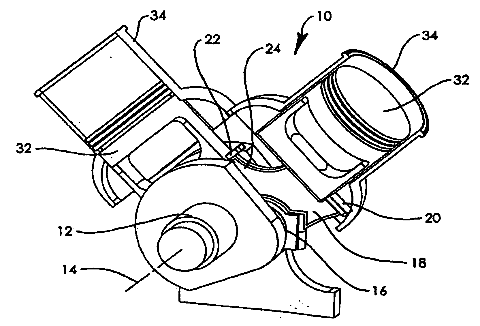
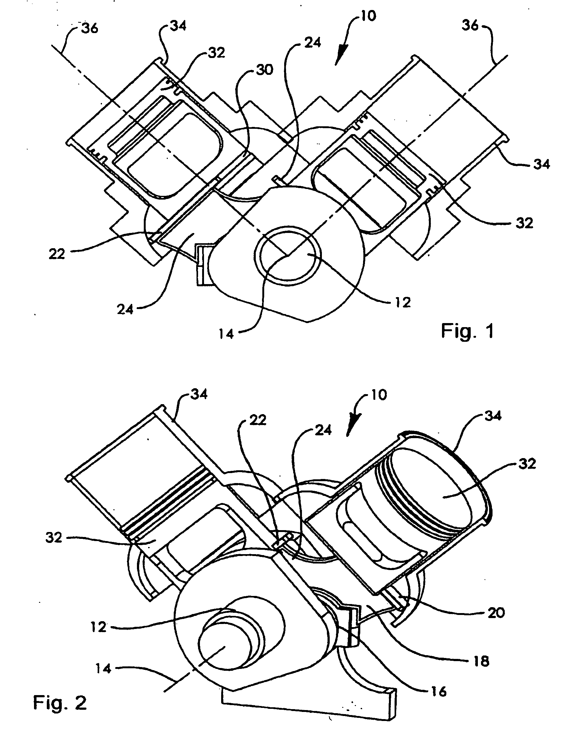
[0217] Referring to FIGS. 1 and 2 there is shown a fluid device 10 which includes a crank 12 mounted for rotation about a crank axis 14. The crank 12 has an offset bearing pin 16, radially distant from the axis 14. Thus as the crank 12 rotates about axis 14, pin 16 will describe a circular orbit around axis 14.

[0218] Rotatably mounted on bearing pin 16 is a slider 18. The slider has two tongues 20, 22.

[0219] The slider 18 extends generally perpendicular to the axis 14 whilst the tongues extend generally parallel to the axis 14. As best seen in FIG. 2 the sliding surfaces extend axially on either side of the main portion 24 of the slider 18 and so form a T-shaped construction.

[0220] Each of the tongues 20, 22 engages in a T-shaped slot 30 of a respective piston 32. Each piston is mounted in a cylinder 34 and constrained for linear movement along a respective cylinder axis 36. Each slot 30 preferably extends substantially perpendicular to the cylinder axis 36 and extends diametrica...


PUM


Abstract

The invention provides a scotch yoke type fluid device which includes a scotch yoke element. The scotch yoke element may be a channel, a rail, a channel and a rail, a bore or a bore and a rail. The scotch yoke element defines a longitudinal path, along which the big end of the device reciprocates, relative to the piston. The device includes restricting means which move along a defined path and which constrain the piston or the scotch yoke element or a connecting rod for the piston to move along the defined path. At least part of the restricting means is located transversely of the longitudinal path of the scotch yoke element, and within the piston footprint.

Description

[0001] This application is a continuation of, and claims the priority of the filing date and foreign priority of U.S. Ser. No. 09 / 937,740, presently pending, which was an application under 35 USC 371 of PCT / AU00 / 00281, filed Apr. 3, 2000.CROSS-REFERENCE TO RELATED APPLICATIONS [0002] The present application is related, in terms of its subject matter, to copending applications Ser. No. 10 / 381,953, having a 35 US 371(c) date of Aug. 22, 2003; and Ser. No. 10 / 476,126, having a 35 US 371(c) date of Jun. 10, 2004, both of which applications are presently pending, and the inventors of which are the same as in the present application. BACKGROUND OF THE INVENTION [0003] 1. Technical Field [0004] This invention relates to a variation of reciprocating fluid machines colloquially called “scotch yoke” devices. [0005] 2. Background Art [0006] Known scotch yoke devices include one or more pairs of horizontally opposed pistons reciprocating in respective cylinders. Each piston of a pair is rigidly...

Claims


Application Information

Patent Timeline
IPC IPC(8): F01B1/00F01B9/02F02B75/32F01B31/04F02B75/22F02B75/24F02F3/00F03C1/02F04B1/04F04B1/047F04B1/053F04B9/04F04B23/00F04B27/047F04B35/01F04B53/00F04B53/14F04B53/16F16C9/02F16H21/36
CPCF01B9/023F02B75/22F02B75/246F16H21/36F04B1/04
Inventor RAFFAELE, PETER ROBERTRAFFAELE, MICHAEL JOHN
Owner RAFFAELE PETER ROBERT
Why Eureka
Try Eureka