Drive control apparatus for forklift
a control apparatus and forklift technology, applied in the direction of tractors, pedestrian/occupant safety arrangements, vehicular safety arrangements, etc., can solve the problems of inability to ensure the driving stability of the forklift, the change of the contents of the limitation is not taken into account, and the forklift is unstable. achieve the effect of ensuring the driving stability of the vehicl
- Summary
- Abstract
- Description
- Claims
- Application Information
AI Technical Summary
Benefits of technology
Problems solved by technology
Method used
Image
Examples
first embodiment
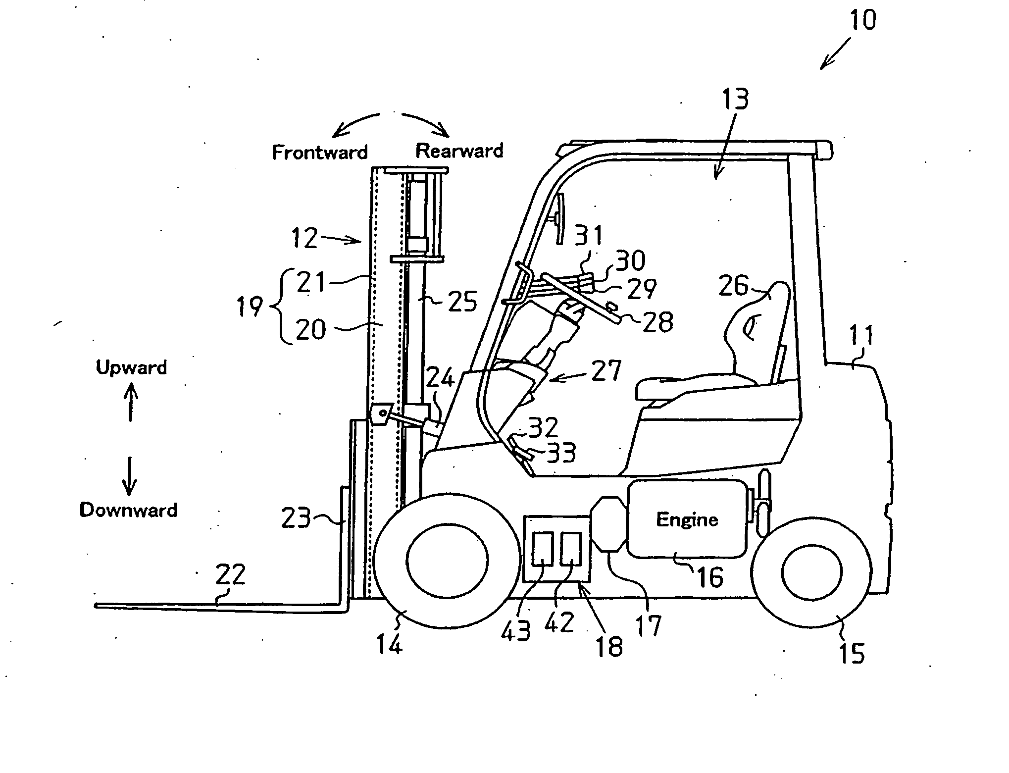
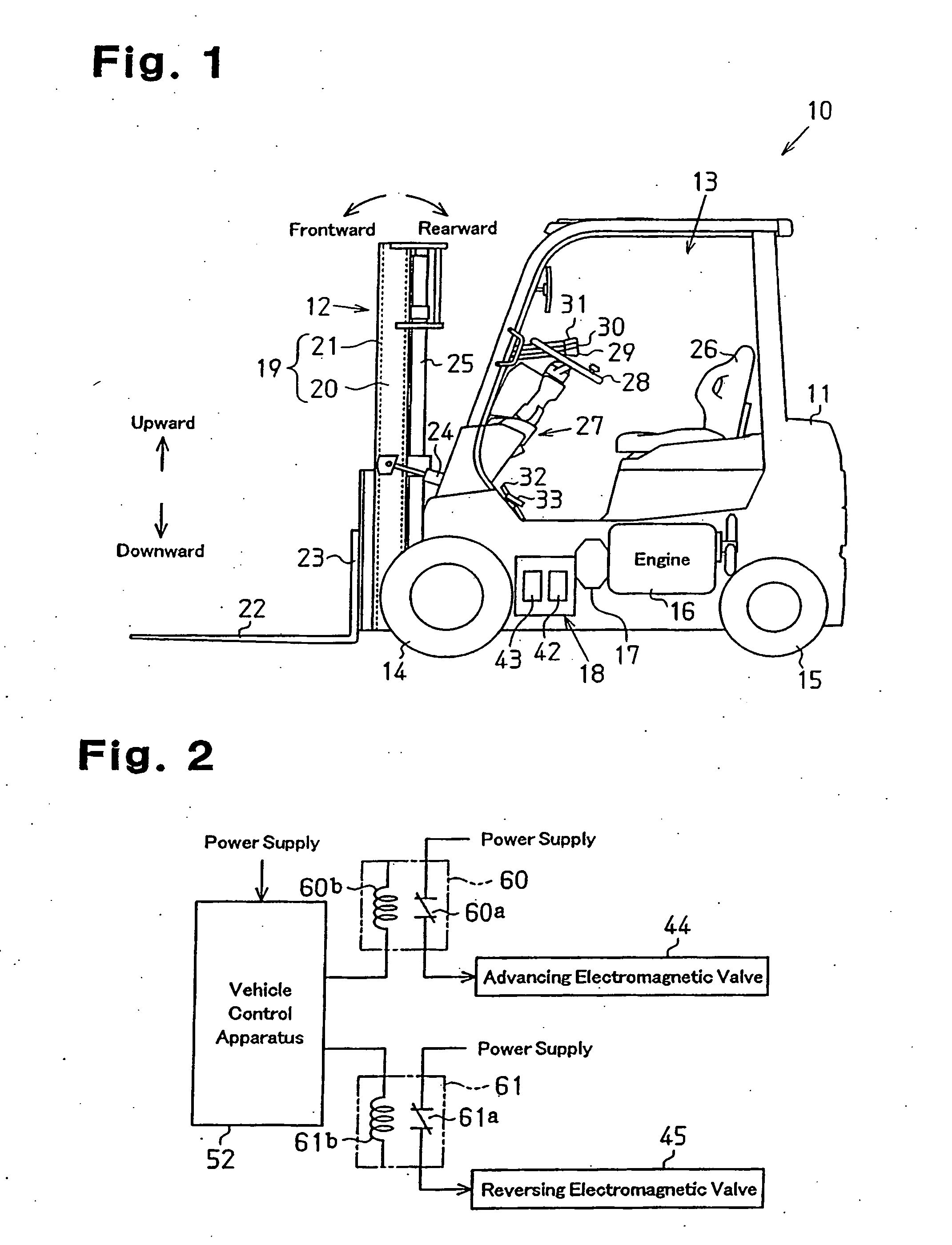
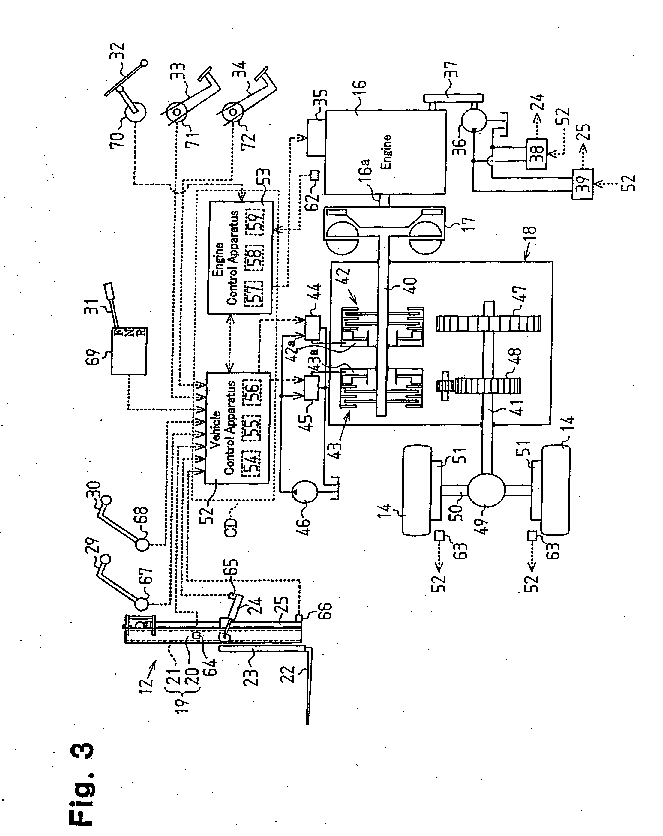
[0026] A drive control apparatus CD for use in a forklift 10 according to a first embodiment of the present invention will now be described with reference to FIGS. 1 to 9.
[0027]FIG. 1 is a side view of the forklift 10. As shown in FIG. 1, the forklift 10 includes a loading device 12 at a front portion of a vehicle body 11. A cab 13 is formed in a center portion of the vehicle body 11. Drive wheels (front wheels) 14 are located in front and lower portions of the vehicle body 11, and steered wheels 15 are provided in rear and lower portions of the vehicle body 11. The vehicle body 11 also mounts a transmission 18 having a torque converter 17. The transmission 18 forms a power transmission mechanism. An engine 16 is coupled to the drive wheels 14 by way of the transmission 18 having the torque converter 17. The transmission 18 is located between the drive wheels 14 and the engine 16. The forklift 10 of this embodiment is an engine type (engine vehicle), in which the drive wheels 14 ar...
second embodiment
[0080] A second embodiment of the present invention will now be described. In the following embodiments, explanations of the same components of the already described embodiment will be omitted or simplified.
[0081]FIG. 10 illustrates the configuration of a forklift 10 according to the present embodiment. As shown in FIG. 10, a wheel angle sensor 81 is provided at one end of an axle 80 of the steered wheels 15. The wheel angle sensor 81 detects a wheel angle that indicates the steered angle of the steered wheels 15. In the present embodiment, the wheel angle sensor 81 is, for example, a potentiometer. The wheel angle sensor 81 is connected to the vehicle control apparatus 52 and outputs a detection signal (wheel angle signal) corresponding to the wheel angle.
[0082] In the forklift 10 of the present embodiment, when the load state is in a region corresponding to the fork height equal to or higher than the height H and the load weight less than the weight W in the necessity determinin...
third embodiment
[0090] A third embodiment of the present invention will now be described. This embodiment may be applied to the first and second embodiments.
[0091] In this embodiment, load fluctuation generated during driving of the forklift 10 is monitored, and a control procedure for changing the contents of limitation on the driving in accordance with the load fluctuation is executed. The load fluctuation in the present embodiment refers to the weight of the load mounted on the loading device 12 (the forks 22). When the forklift 10 is moving, the accompanying vibration causes a load to vibrate, and the value of a detection signal outputted by the load sensor 66 is less stable than the case where the forklift 10 is not moving. Therefore, in the limitation determining process shown in FIG. 7, the contents of limitation is likely to be repeatedly changed during driving by the influence of the detection signal indicating the load weight obtained at step S10 (influence of load fluctuation). Referrin...
PUM
 Abstract
Description
Claims
Application Information
 - R&D
- Intellectual Property
- Life Sciences
- Materials
- Tech Scout
- Unparalleled Data Quality
- Higher Quality Content
- 60% Fewer Hallucinations
Browse by: Latest US Patents, China's latest patents, Technical Efficacy Thesaurus, Application Domain, Technology Topic, Popular Technical Reports.
© 2025 PatSnap. All rights reserved.Legal|Privacy policy|Modern Slavery Act Transparency Statement|Sitemap|About US| Contact US: help@patsnap.com


