Pneumatic tire manufacturing method and pneumatic tire

一种充气轮胎、制造方法的技术,应用在轮胎胎面/胎面花纹、轮胎零部件、胎等方向,能够解决高负载区域驾驶稳定性能下降、性能的改善效果不充分等问题,达到提高驾驶稳定性能、刚性提高、衰减性提高的效果

Active Publication Date: 2015-04-15
TOYO TIRE & RUBBER CO LTD
View PDF8 Cites 8 Cited by
  • Summary
  • Abstract
  • Description
  • Claims
  • Application Information

AI Technical Summary

Problems solved by technology

[0007] (2) There are cases in which specific rubber is separately arranged in the shoulder area or the outer area, so that the performance improvement effect is not sufficient
For example, if in Figure 8 In the tread rubber 80, in order to improve driving stability, a hard rubber 81 is arranged in the central area, and in order to improve riding comfort or noise performance, a soft rubber 82 is arranged in the shoulder area, which has the advantages of being in the low load area. The driving stability performance of the vehicle is improved, but the driving stability performance in the high load area tends to decrease

Method used


Image

  • Pneumatic tire manufacturing method and pneumatic tire
  • Pneumatic tire manufacturing method and pneumatic tire
  • Pneumatic tire manufacturing method and pneumatic tire

Examples


no. 1 approach

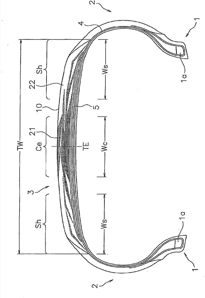
[0057] figure 1 The illustrated pneumatic tire includes: a pair of bead portions 1; sidewall portions 2 extending outward in the tire radial direction from the respective bead portions 1; end connection. A reinforcing material such as a belt layer 5 is disposed on the outer periphery of the carcass layer 4 formed in a ring shape, and a tread rubber 10 is provided to cover the reinforcing material. Although not shown, the outer peripheral surface of the tread rubber 10 is provided with: grooves such as longitudinal grooves or horizontal grooves; conditions corresponding to the tread pattern.

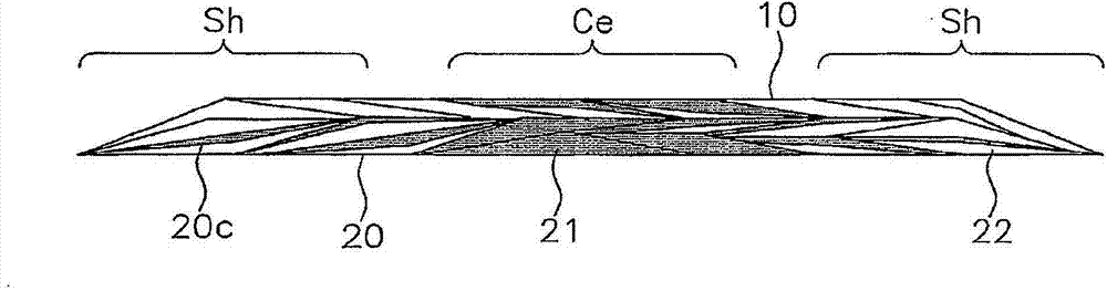
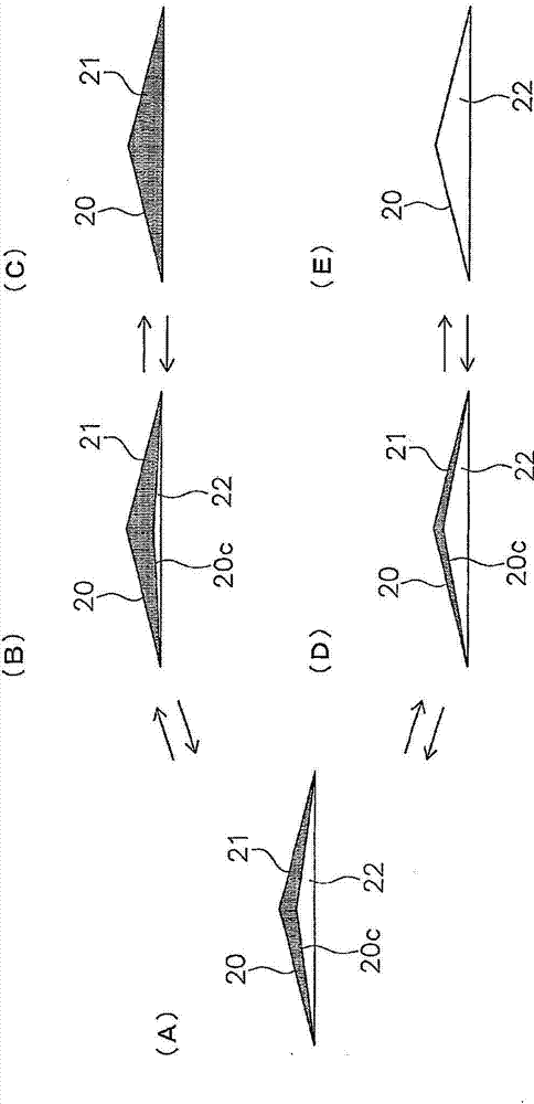
[0058] The tread rubber 10 is composed of a rubber belt wound body formed by helically winding a rubber belt, and is formed by a belt winding method described later. In this tread rubber 10, in the center region Ce (corresponding to the first region) located at the central part in the tread width direction and the shoulder regions Sh (corresponding to the second region) at the end par...

no. 2 approach

[0081] Since the second embodiment is the same as the first embodiment except for the items described below, common points will be omitted and differences will be mainly described. The same reference numerals are assigned to the same components or parts as those described in the first embodiment, and repeated descriptions will be omitted.

[0082] Image 6 It is a view showing the tread rubber 11 before vulcanization, and schematically depicts a cross section of the rubber belt 20 constituting the rubber belt wound body. In this tread rubber 11, an inner region In (corresponding to the first region) located on one side in the tread width direction which becomes the vehicle inner side when the vehicle is mounted, and the other side in the tread width direction which becomes the vehicle outer side when the vehicle is mounted. The outer area Out (corresponding to the second area) on one side is mainly equipped with different rubber. That is, the rubber 21 (corresponding to the ...


PUM


Abstract

A method of manufacturing a pneumatic tire has a winding step of forming a rubber ribbon winding body constructing a tread rubber by spirally winding a rubber ribbon obtained by co-extruding a first rubber and a second rubber which are different in hardness. The first rubber is mainly arranged in a first area by making a cross sectional area ratio of the first rubber greater than that of the second rubber. The second rubber is mainly arranged in a second area by making the cross sectional area ratio of the first rubber smaller than that of the second rubber. A portion in which the cross sectional area ratio of the first rubber becomes smaller by smaller is provided from the first area toward the second area. The rubber ribbon retaining a compound interface is superposed and wound to at least a part of the second area.

Description

technical field [0001] The present invention relates to a method of manufacturing a pneumatic tire including a process of molding tread rubber by a belt-to-roll method, and a pneumatic tire manufactured by the manufacturing method. Background technique [0002] As disclosed in Patent Documents 1 and 2, it is known to divide the tread rubber into a plurality of regions in the tread width direction and arrange rubbers having different hardness or coefficients in these regions. [0003] Figure 8 Shown is the tread rubber 80 divided into three parts, namely, a center region serving as a central portion in the tread width direction, and a pair of shoulder regions serving as end portions in the tread width direction. This division of the tread promotes performance sharing in the center region and the shoulder region, whereby a high balance of opposite performances can be achieved. For example, in the tire described in Patent Document 1, hard rubber is arranged in the center regi...

Claims


Application Information

Patent Timeline
Patent Type & Authority Applications(China)
IPC IPC(8): B60C11/00B29C48/21B29C48/49
CPCB60C11/0041B29C47/06B60C2011/0025B29C47/0038B60C11/0008B60C2011/0091B29D30/60B29D30/3035B60C11/0066B29K2021/00B29C48/07B29C48/12B29C48/0021B29C48/21B29C48/387B29C48/49B29C2948/9258B29C2948/9259B29C2948/92885B29C2948/92933B29C2948/92952B29C48/18B29D30/3028
Inventor 下村和生
Owner TOYO TIRE & RUBBER CO LTD
Why Eureka
Try Eureka