Methods and apparatus for practical 3D vision system

a 3d vision and system technology, applied in the field of machine vision, can solve the problems of requiring manual intervention, requiring too much processor power to be practical for real-time application, and requiring contact, etc., and achieves the effects of speeding up performance and robustness, convenient use, and easy setup

Active Publication Date: 2007-04-12
COGNEX TECH & INVESTMENT
View PDF99 Cites 100 Cited by
  • Summary
  • Abstract
  • Description
  • Claims
  • Application Information

AI Technical Summary

Benefits of technology

[0025] Further related aspects of the invention provide such methods in which training as to expected patterns includes utilizing—within the functionality associated with each camera—different models for like patterns as between different cameras. This facilitates finding patterns, e.g., when pose, viewing angle and / or obstructions alter the way that different cameras will image those patterns.
[0029] Still further aspects of the invention provide methods as described above in which the training step acquires multiple views of the object for each camera, preferably, such that the origins of the patterns found on those objects are consistently defined. To account for potential inconsistency among images, that produce the highest match score for the patterns can be used. This has the benefit of making the methodology more robust to finding parts in arbitrary poses.
[0032] Other aspects of the invention provide methods as described above in which functionality associated with the cameras “times out” if it fails to find an expected pattern in an image of an object—during training or runtime—thereby avoiding undue delay in position determination, e.g., if such a pattern is missing, occluded or otherwise not detected.
[0039] Advantages of systems and methods according to the invention are that they are easier to use and more practical than prior art systems approaches—yet, are vision-based and, hence, do not require contact with or prior preparation of objects subject to inspection. Such systems and methods (according to the invention) can be easily setup, and then trained using “show-and-go”.
[0040] In addition, they provide speedy performance and robustness, e.g., with respect to missing and incorrect results. Thus, for example, methods and apparatus according to aspects of the invention can determine the pose of objects even though some patterns are not found in some (and, under some circumstances, any) of the runtime images, e.g., because the patterns are occluded from view by one or more cameras or because images of those patterns could not be timely acquired. By way of further example, methods and apparatus according to aspects of the invention provide robustness with respect to incorrect results (e.g., caused by misaligned cameras) by triangulating using subsets of the 3D locations corresponding patterns found in runtime images: if one of the subsets results in a lower sum-squared error, that subset can be used for position triangulation, rather than all of the patterns.

Problems solved by technology

Some require too much processor power to be practical for real-time application.
However, this requires contact, is relatively slow and can require manual intervention.
These do not require physical contact, but suffer their own drawbacks, such as requiring the oft impractical step of affixing transmitters to objects that are subject to inspection.

Method used


Image

  • Methods and apparatus for practical 3D vision system
  • Methods and apparatus for practical 3D vision system
  • Methods and apparatus for practical 3D vision system

Examples


Embodiment Construction

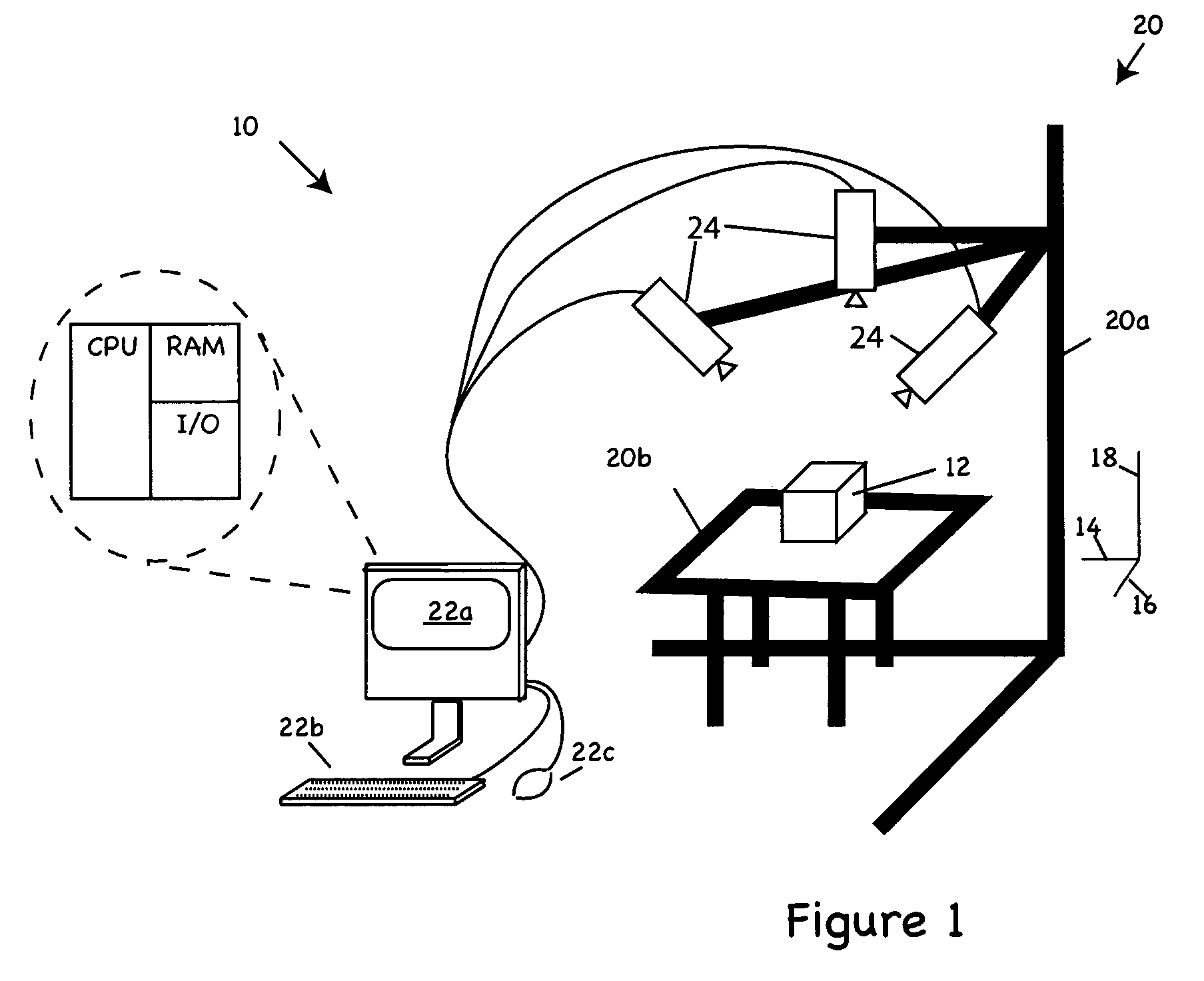
[0046]FIG. 1 depicts a machine vision system 10 according to the invention capable of determining the pose of an object 12 in three dimensions by triangulation of data gleaned from multiple images of the object. In the illustrated embodiment, the pose is defined position and orientation of the object in three-dimensional space—or, more precisely, the position of the object along x-, y- and z-axes 14, 16, 18 as well the object's pitch, roll and yaw relative thereto. In other embodiments, pose might be limited to subsets of these spatial characteristics (e.g., position along axis 16 and yaw; position along axes 14-18; roll; etc.). Illustrated axes 14-18 are aligned with a frame 20 of the vision system 10; though, in other embodiments, other frames of reference may be used. Frame 20 of the illustrated embodiment is figuratively represented by camera mounts 20a and platform 20b depicted with heavy shading; though, in other embodiments, other or no such members need be employed.

[0047] S...


PUM


Abstract

The invention provides inter alia methods and apparatus for determining the pose, e.g., position along x-, y- and z-axes, pitch, roll and yaw (or one or more characteristics of that pose) of an object in three dimensions by triangulation of data gleaned from multiple images of the object. Thus, for example, in one aspect, the invention provides a method for 3D machine vision in which, during a calibration step, multiple cameras disposed to acquire images of the object from different respective viewpoints are calibrated to discern a mapping function that identifies rays in 3D space emanating from each respective camera's lens that correspond to pixel locations in that camera's field of view. In a training step, functionality associated with the cameras is trained to recognize expected patterns in images to be acquired of the object. A runtime step triangulates locations in 3D space of one or more of those patterns from pixel-wise positions of those patterns in images of the object and from the mappings discerned during calibration step.

Description

BACKGROUND OF THE INVENTION [0001] The invention pertains to machine vision and, more particularly, three-dimensional (3D) machine vision. The invention has application in manufacturing, quality control, and robotics, to name but a few fields. [0002] Machine vision refers to the automated analysis of images to determine characteristics of objects represented in them. It is often employed in automated manufacturing lines, where images of components are analyzed to facilitate part-picking, as well as to determine part placement and alignment for assembly. When robots are the means for automated assembly and automated analysis of images is used to facilitate part picking, placement, and alignment, the system is referred to as vision-guided robotics. Machine vision is also used for robot navigation, e.g., to insure the recognition of scenes as robots travel through environments. [0003] Though three-dimensional (3D) analysis has long been discussed in the literature, most present-day mac...

Claims


Application Information

Patent Timeline
Patent Type & Authority Applications(United States)
IPC IPC(8): G06K9/00G06V10/147
CPCG06K9/209G06K2209/19G06V10/147G06V2201/06
Inventor WALLACK, AARON S.MICHAEL, DAVID
Owner COGNEX TECH & INVESTMENT
Why Eureka
Try Eureka