Fluidized positioning and protection system

a protection system and positioning technology, applied in the field of body parts supporting, can solve the problems of potentially more damaging to skin integrity by friction and shear, and achieve the effect of positive

Inactive Publication Date: 2007-04-19
SUNDANCE ENTERPRISES
View PDF30 Cites 39 Cited by
  • Summary
  • Abstract
  • Description
  • Claims
  • Application Information

AI Technical Summary

Benefits of technology

This patent describes an improved medical positioning system that helps with various bodily functions such as blood flow, brain function, bones, stomach, breathing, and lungs. It's designed to be both strong enough to hold up patients and gentle enough to avoid harming delicate organs like veins and nerves.

Problems solved by technology

The technical problem addressed in this patent text is how to provide effective positioning and cushoning for patients in hospitals without using traditional foam and gel materials which can only react to force in one direction (either twisting or sliding). There is also an increasing demand for products that can accommodate both types of movement at once.

Method used


Image

  • Fluidized positioning and protection system
  • Fluidized positioning and protection system
  • Fluidized positioning and protection system

Examples


Embodiment Construction

[0055] Reference will now be made in greater detail to a preferred embodiment of the invention, an example of which is illustrated in the accompanying drawings. Wherever possible, the same reference numerals will be used throughout the drawings and the description to refer to the same or like parts.

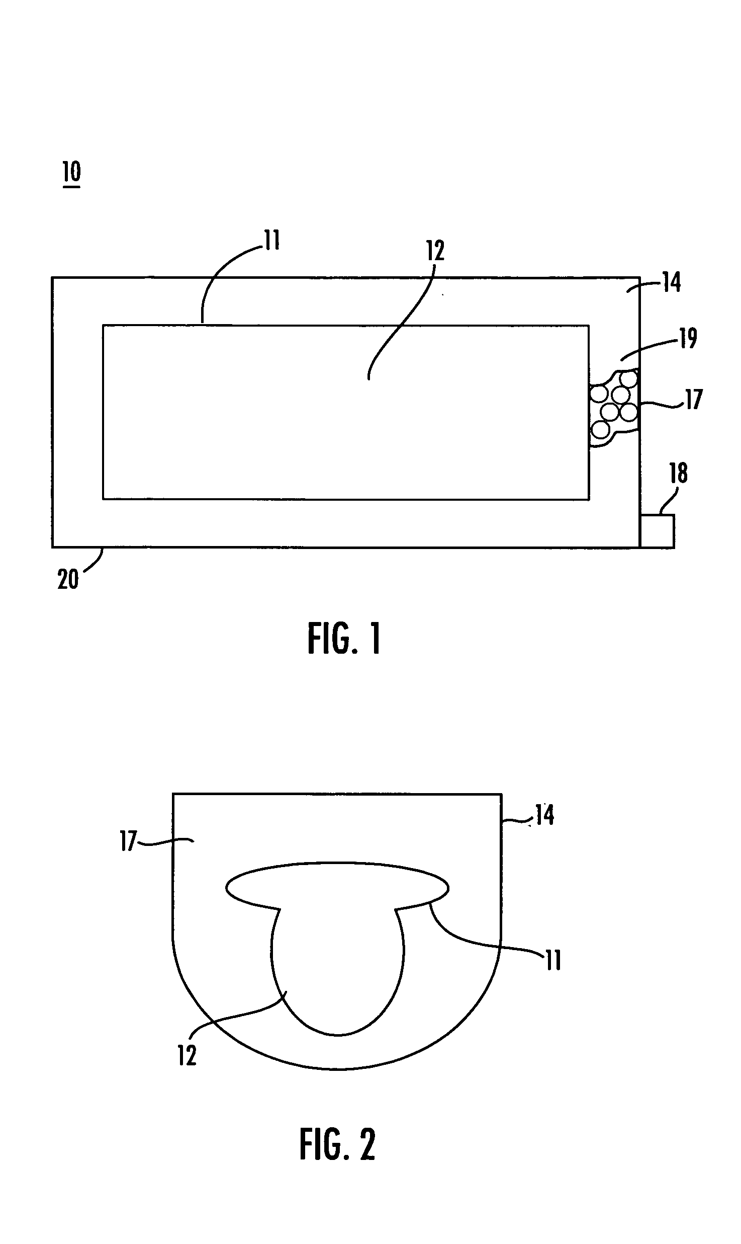
[0056]FIG. 1 is a top plan view of a fluidized positioning and protection system 10 in accordance with the teachings of the present invention. Inner bladder 11 is filled with composition 12 which can retain its shape after sculpting. For example, inner bladder 11 can be formed of a flexible plastic, such as urethane. Composition 12 refers to a compound or composition which can be sculpted and retain its shape and has no memory or substantially no memory. The no memory or substantially no memory feature enables inner bladder 11 to increase in height and maintain support of a body part. Inner bladder 11 provides micro-contouring because composition 12 can respond three dimensionally. Compo...


PUM


Abstract

The present invention provides a fluidized positioning system including an inner bladder formed of a medium that has no memory or substantially no memory. An outer bladder is placed adjacent to or coupled to the inner bladder. The outer bladder is partially filled with a composition. The composition can be beads, such as polystyrene beads, or beads made of a similar medium. A valve extending from the outer bladder permits the evacuation of all or some of the air from the outer bladder which causes the outer bladder to be reduced in size due to loss of air between the beads and adjusts the rigidity of the outer bladder to allow the outer bladder to form fit the inner bladder around whatever body extremity it is being used on.

Description


Claims


Application Information

Patent Timeline
Owner SUNDANCE ENTERPRISES
Why Eureka
Try Eureka