Transmitting arrangement and method for impedance matching

a technology of impedance matching and transmission arrangement, applied in the direction of impedence matching networks, modulation, multi-port active networks, etc., can solve the problem of mismatching the power transistor to the impedance value of the antenna

Active Publication Date: 2007-04-19
INTEL CORP
View PDF7 Cites 109 Cited by
  • Summary
  • Abstract
  • Description
  • Claims
  • Application Information

AI Technical Summary

Problems solved by technology

The characteristics of a real antenna which change in operation can cause a mismatch of the power transistor to an impedance value of the antenna.

Method used


Image

  • Transmitting arrangement and method for impedance matching
  • Transmitting arrangement and method for impedance matching
  • Transmitting arrangement and method for impedance matching

Examples


Embodiment Construction

[0014] One or more examples will now be described with reference to the drawing figures, wherein like reference numerals are used to refer to like elements throughout. It should be understood that the drawing figures and following descriptions are merely illustrative and that they should not be taken in a limiting sense. In the following description, for purposes of explanation, numerous specific details are set forth in order to provide a thorough understanding. It will be appreciated that variations of the illustrated systems and methods apart from those illustrated and described herein may exist and that such variations are deemed as falling within the scope of the appended claims

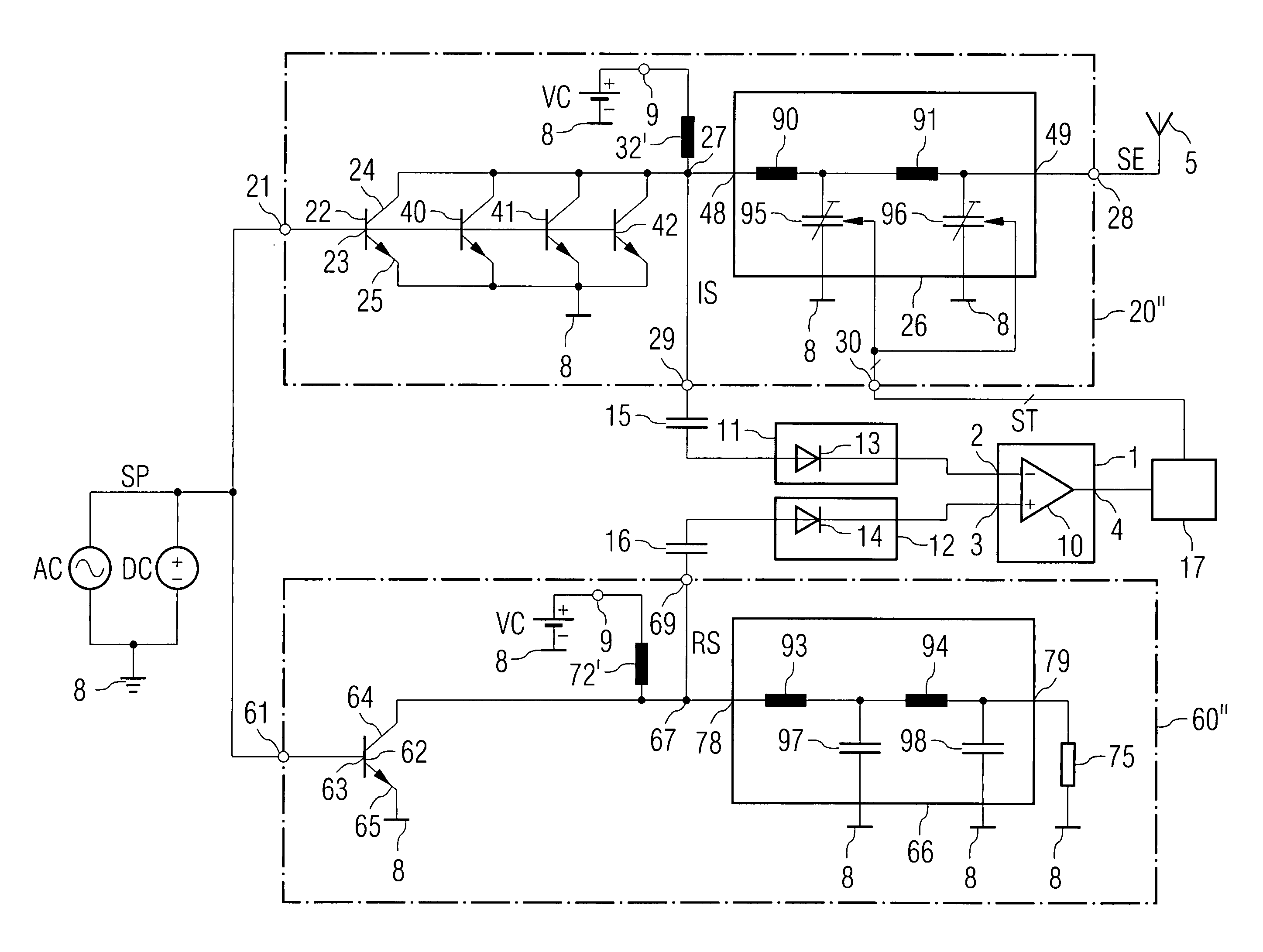
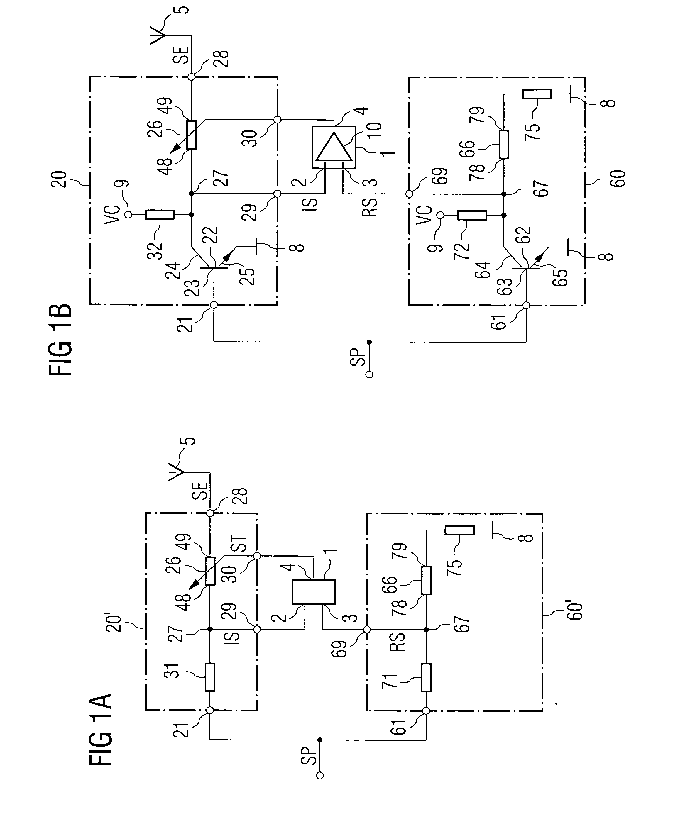
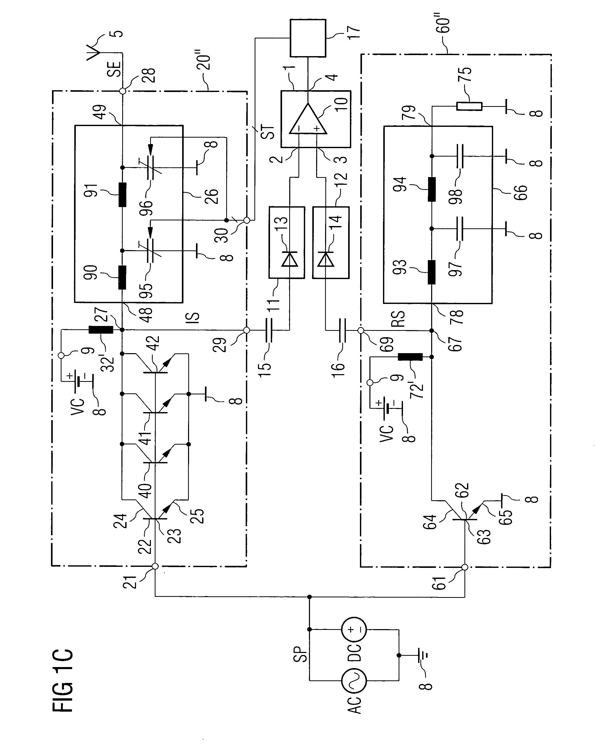
[0015]FIG. 1A illustrates an example of a transmitting arrangement. The transmitting arrangement comprises a matching circuit 20′ and a reference circuit 60′. An antenna 5 is coupled to an output 28 of the matching circuit 20′. The matching circuit 20′ has an input 21. The input 21 of the matching circu...


PUM


Abstract

A transmitting arrangement includes a matching circuit, a reference circuit and a comparator. The output of the matching circuit can be coupled to an antenna and comprises an adjustable impedance. The reference circuit is connected to an input of the matching circuit and comprises a reference impedance. Inputs of the comparator are coupled to the matching circuit and the reference circuit and its output is coupled to the adjustable impedance via a control input of the matching circuit.

Description

REFERENCE TO RELATED APPLICATIONS [0001] This application claims the benefit of the priority date of German application DE 10 2005 047 155.2, filed on Sep. 30, 2005, the contents of which are herein incorporated by reference in their entirety. FIELD OF THE INVENTION [0002] Transmitting arrangements, the use of a transmitting arrangement and a method for impedance matching are disclosed. BACKGROUND OF THE INVENTION [0003] Transmitting arrangements, particularly in devices of mobile radio communication, usually have a power transistor which is followed by an antenna. The characteristics of a real antenna which change in operation can cause a mismatch of the power transistor to an impedance value of the antenna. The cause of such changes is mainly the changes in the environmental conditions of the antenna caused by the user of a device of the mobile radio communication. The device can be located, for example, in a hand, on a metallic base or in a vehicle. SUMMARY OF THE INVENTION [0004...

Claims


Application Information

Patent Timeline
Patent Type & Authority Applications(United States)
IPC IPC(8): H03F3/04
CPCH03H11/30
Inventor ITKIN, GRIGORYADLER, BERND
Owner INTEL CORP
Why Eureka
Try Eureka