Radio frequency lens and method of suppressing side-lobes

a radio frequency lens and sidelobe technology, applied in the direction of antennas, electrical equipment, etc., can solve problems such as creating errors within the wavefront, and achieve the effect of reducing the amount of energy

Active Publication Date: 2010-08-17
HARRIS CORP
View PDF34 Cites 166 Cited by
  • Summary
  • Abstract
  • Description
  • Claims
  • Application Information

AI Technical Summary

Benefits of technology

[0005]According to present invention embodiments, an RF lens collimates an RF beam by refracting the beam into a beam profile that is diffraction-limited. The lens is constructed of a lightweight mechanical arrangement of two or more materials, where the materials are arranged to form a photonic crystal structure (e.g., a series of holes defined within a parent material). The lens includes impedance matching layers, while an absorptive or apodizing mask is applied to the lens to create a specific energy profile across the lens. The impedance matching layers and apodizing mask similarly include a photonic crystal structure. The energy profile function across the lens aperture is continuous, while the derivatives of the energy distribution function are similarly continuous. This lens arrangement produces a substantial reduction in the amount of energy that is transmitted in the side-lobes of an RF system.
[0006]The photonic crystal structure of the present invention embodiments provides several advantages. In particular, the lens structure provides for precise control of the phase error across the aperture (or phase taper at the aperture) simply by changing the spacing and size of the hole patterns. This enables the lens to be designed with diffraction-limited wavefront qualities, thereby assuring the tightest possible beams. Further, the inherent lightweight nature of the lens parent material (and holes defined therein) enables creation of an RF lens that is lighter than a corresponding solid counterpart. The structural shape of the holes enables the lens to contain greater structural integrity at the rim portions than that of a lens with similar function typically being thin at the edges. This type of thin-edge lens may droop slightly, thereby creating errors within the wavefront. Moreover, the photonic crystal structure is generally flat or planar, thereby providing for simple manufacture, preferably through the use of computer-aided fabrication techniques. In addition, the photonic crystal structure effects steering of the entire RF beam without creating (or with substantially reduced) side-lobes.

Problems solved by technology

This type of thin-edge lens may droop slightly, thereby creating errors within the wavefront.

Method used


Image

  • Radio frequency lens and method of suppressing side-lobes
  • Radio frequency lens and method of suppressing side-lobes
  • Radio frequency lens and method of suppressing side-lobes

Examples


Embodiment Construction

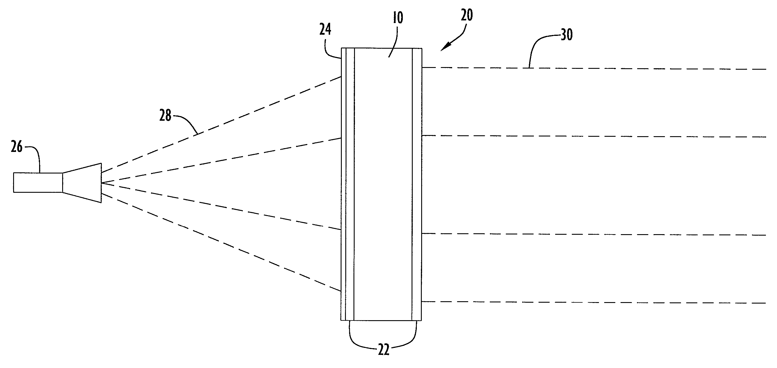
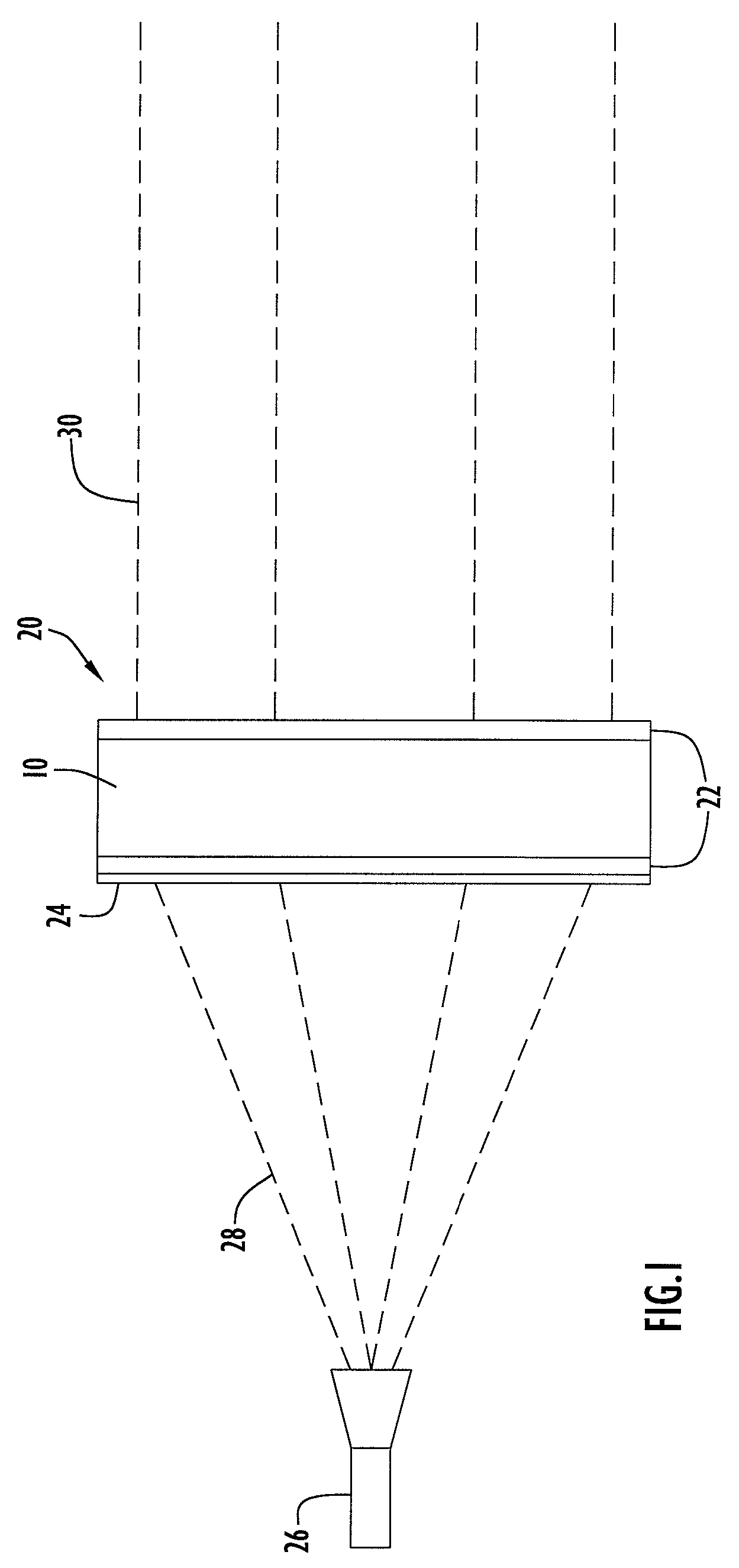
[0018]The present invention embodiments pertain to a radio frequency (RF) lens that includes a photonic crystal structure and suppresses side-lobe features. An exemplary lens according to an embodiment of the present invention being illuminated by an RF signal source or feed horn is illustrated in FIG. 1. Specifically, the configuration includes a signal source 26 and an RF lens 20 according to an embodiment of the present invention. Signal source 26 may be implemented by any conventional or other signal source (e.g., feed horn, antenna, etc.) and preferably provides an RF signal or beam 28. Lens 20 receives the RF beam from signal source 26 and refracts the beam to produce a collimated RF beam 30. Lens 20 may be utilized for any suitable RF transmission and / or reception system.

[0019]Lens 20 includes a lens portion or layer 10, a plurality of impedance matching layers 22 and an absorption or apodizing layer or mask 24. Lens layer 10 is disposed between and attached to impedance matc...


PUM


Abstract

An RF lens according to the present invention embodiments collimates an RF beam by refracting the beam into a beam profile that is diffraction-limited. The lens is constructed of a lightweight mechanical arrangement of two or more materials, where the materials are arranged to form a photonic crystal structure (e.g., a series of holes defined within a parent material). The lens includes impedance matching layers, while an absorptive or apodizing mask is applied to the lens to create a specific energy profile across the lens. The impedance matching layers and apodizing mask similarly include a photonic crystal structure. The energy profile function across the lens aperture is continuous, while the derivatives of the energy distribution function are similarly continuous. This lens arrangement produces a substantial reduction in the amount of energy that is transmitted in the side-lobes of an RF system.

Description

BACKGROUND OF THE INVENTION[0001]1. Technical Field[0002]The present invention pertains to lenses for radio frequency transmissions. In particular, the present invention pertains to a radio frequency (RF) lens that includes a photonic crystal structure and suppresses side-lobe features.[0003]2. Discussion of Related Art[0004]Radio frequency (RF) transmission systems generally employ dish antennas that reflect RF signals to transmit an outgoing collimated beam. However, these types of antennas tend to transmit a substantial amount of energy within side-lobes. Side-lobes are the portion of an RF beam that are dictated by diffraction as being necessary to propagate the beam from the aperture of the antenna. Typically, suppression of the side-lobe energy is problematic for RF systems that are required to be tolerant of jamming, and is critical for reducing the probability that the transmitted beam is detected (e.g., an RF beam is less likely to be detected, jammed or eavesdropped in res...

Claims


Application Information

Patent Timeline
Patent Type & Authority Patents(United States)
IPC IPC(8): H01Q15/02
CPCH01Q15/08H01Q15/10H01Q17/00H01Q19/06H01Q15/02
Inventor WINSOR, ROBERT SCOTT
Owner HARRIS CORP
Why Eureka
Try Eureka