Impedance matching network and multidimensional electromagnetic field coil for a transponder interrogator

a multi-dimensional electromagnetic field coil and transponder technology, applied in the direction of burglar alarm mechanical actuation, burglar alarm by hand-portable object removal, instruments, etc., can solve the problems of inductive coupling, particularly cost-effective passive transponder, negligible inductive coupling,

Inactive Publication Date: 2005-02-03
AVID INDENTIFICATION SYST
View PDF71 Cites 169 Cited by
  • Summary
  • Abstract
  • Description
  • Claims
  • Application Information

AI Technical Summary

Benefits of technology

In accordance with the teachings of the present invention, an impedance matching network and multidimensional electromagnetic field coil for an interrogator are provided. The improved interrogator provides a multidimensional electromagnetic field through two coils aligned preferably perpendicularly to each other. The coils are energized so as to provide a rotating magnetic field having approximately constant amplitude regardless of its orientation with respect to the transponder. An additional coil may be provided to precess the rotating magnetic field. The interrogator may further provide an impedance matching network that includes a series drive capacitor to match the impedance of a capacitor in parallel with a coil (parallel resonant tank circuit) to a driver's output impedance.

Problems solved by technology

Passive transponders are particularly cost effective because they lack an internal power source.
A drawback of conventional inductively coupled identification systems is that the inductive coupling between the transponder's inductive coil and the electromagnetic field, generated by the interrogator's field coil, may depend on the relative angle between the interrogator's field coil and the transponder's inductive coil.
However, if they are perpendicular, then inductive coupling is negligible and the inductive coupling is less effective.
If the transponder's inductive coil is oriented nearly perpendicular to the magnetic field generated by the interrogator, there may be insufficient inductive coupling for correct operation.
Thus, the interrogator may be unable to obtain the data within a transponder, even though it is within the interrogator's electromagnetic field range, because the interrogator's field coil and the transponder's inductive coil are not properly aligned.
Another drawback of inductively coupled identification systems is the antenna impedance matching network.
This process repeats with losses generally due to the parasitic resistances of the components.
In general, there are many practical problems with operating above 500-1000 Volts: capacitors are expensive, corona and leakage currents consume power, and PC board traces must be widely spaced.
Additionally, the current may become large and difficult to effectively manage.

Method used


Image

  • Impedance matching network and multidimensional electromagnetic field coil for a transponder interrogator
  • Impedance matching network and multidimensional electromagnetic field coil for a transponder interrogator
  • Impedance matching network and multidimensional electromagnetic field coil for a transponder interrogator

Examples


first embodiment

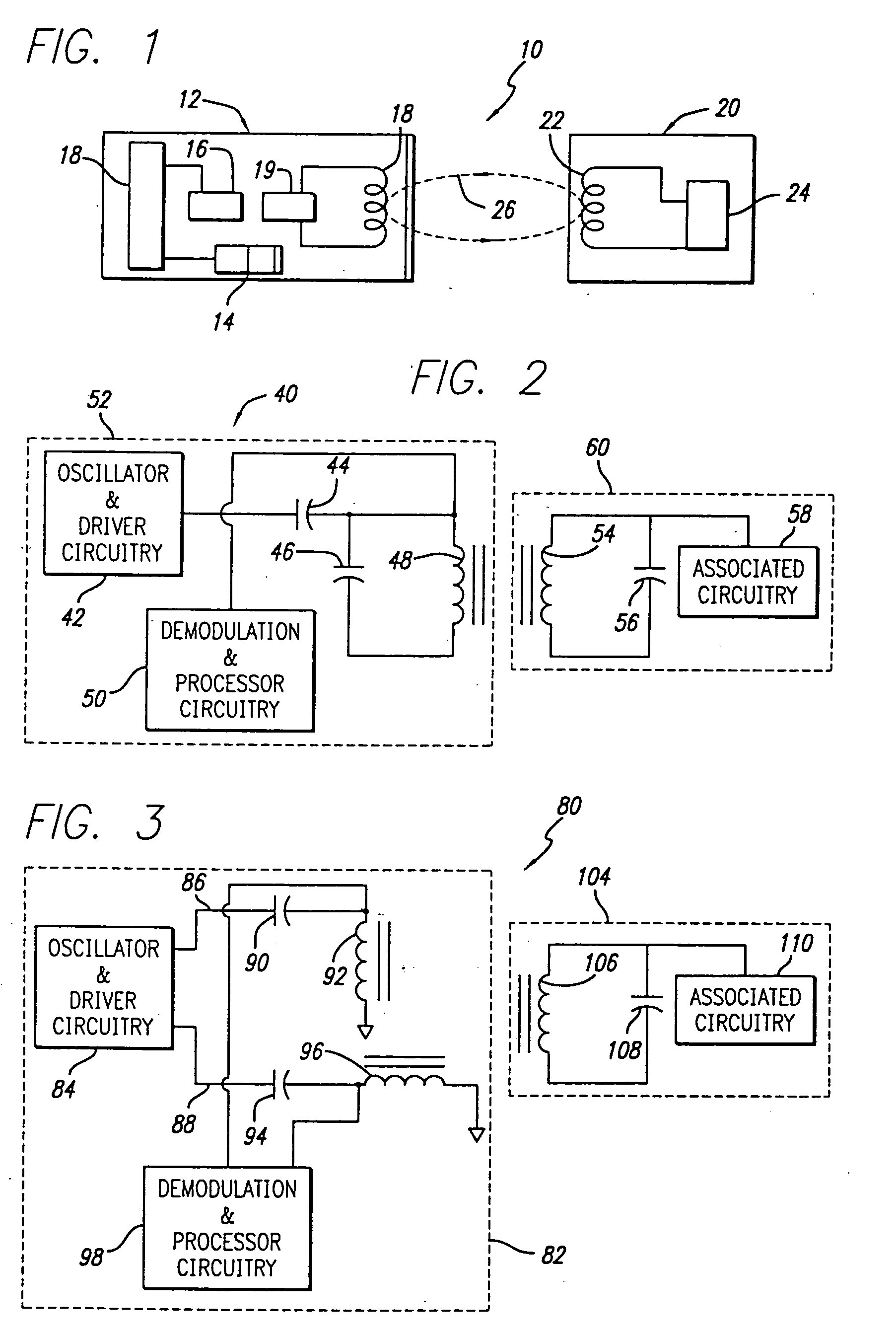
FIG. 2 shows a block diagram of an antenna impedance matching network for an inductively coupled identification system 40 in accordance with the present invention. The identification system 40 includes an interrogator 52 and a transponder 60. The interrogator 52 includes various associated oscillator and coil driver circuitry 42 that provides a signal to a series drive capacitor 44 and then to a tank capacitor 46 and a coil 48. The series drive capacitor 44, the tank capacitor 46, and the coil 48 may be viewed as the emitter for an inductive coupling device, such as the interrogator 52. The signal from the transponder 60 is picked up from the coil 48 and demodulation and processor circuitry 50 process the signal into the desired form for a user of the interrogator 52. The transponder 60 includes a coil 54 and a tank capacitor 56 that is linked to associated circuitry 58. The coil 48 and the coil 54 inductively couple so that the interrogator 52 can read the information stored within...

second embodiment

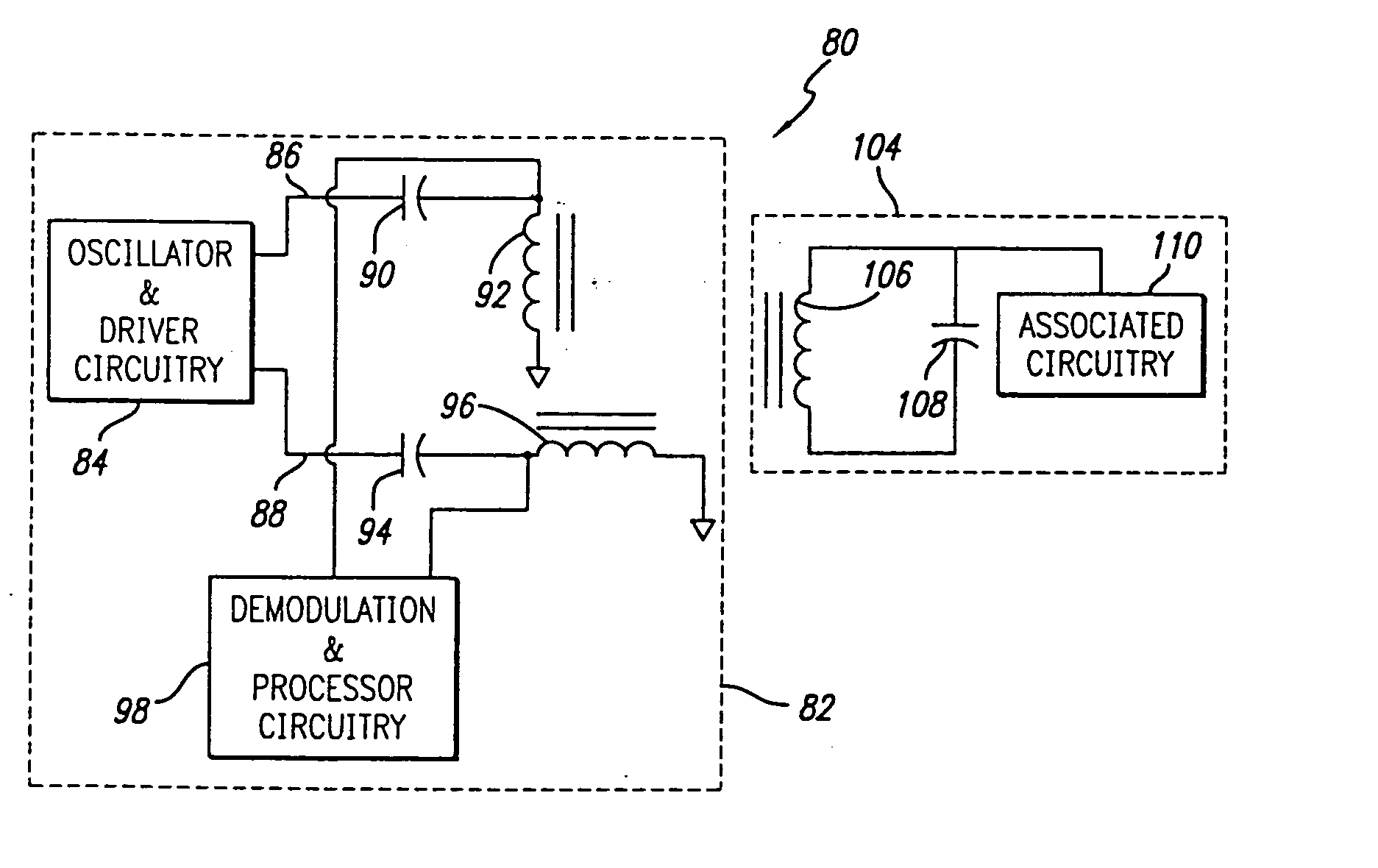
FIG. 3 shows a block diagram of a multidimensional electromagnetic field coil for an inductively coupled identification system 80 in accordance with the present invention. The identification system 80 includes an interrogator 82 and a transponder 104. The interrogator 82 includes various associated oscillator and coil driver circuitry 84 that provides an in-phase channel 86 and a quadrature-phase channel 88. The in-phase channel 86 provides a signal to a series resonant circuit that includes a series capacitor 90 and a coil 92. The quadrature-phase channel 88 provides a signal to a series resonant circuit that includes a series capacitor 94 and a coil 96. The coil 92 and the coil 96 are aligned preferably perpendicular to each other.

The transponder 104 includes a coil 106 and a tank capacitor 108 that is linked to associated circuitry 110. Similarly as discussed above, the coil 92 and / or the coil 96 inductively couple with the coil 106 so that the interrogator 82 can read the infor...

third embodiment

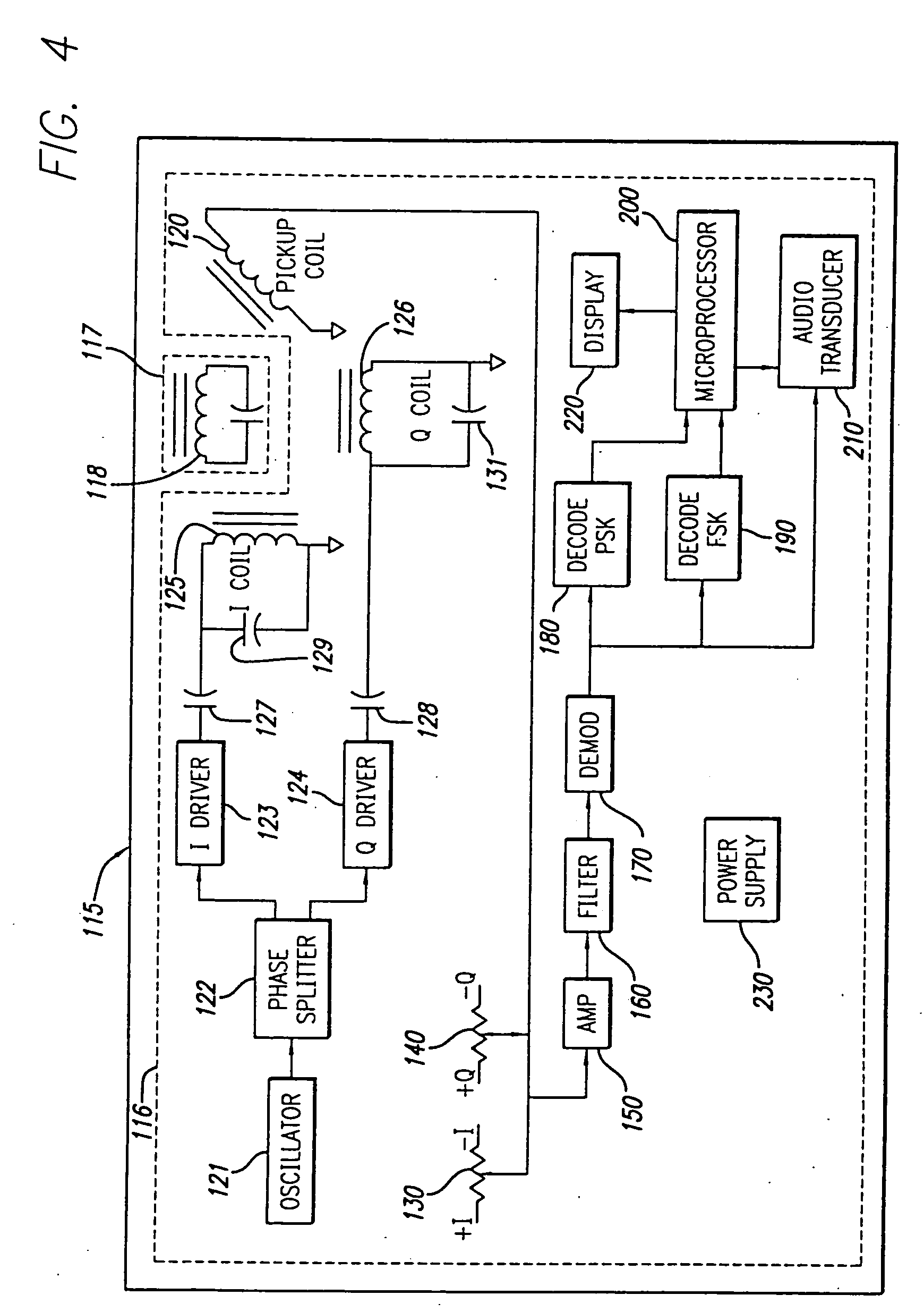
FIG. 4 shows a block diagram of an inductively coupled identification system 115 utilizing an antenna impedance matching network and a multidimensional electromagnetic field coil in accordance with the present invention. The identification system 115 comprises an interrogator 116 and a transponder 117. The interrogator 116 includes an oscillator 121 that generates twice the carrier frequency, which is divided by two and split into two signals 90 degrees apart (in-phase and quadrature phase) by a phase splitter 122. The in-phase signal is sent to an in-phase (I) driver 123 and the quadrature phase signal is sent to a quadrature phase (Q) driver 124, where the signals are amplified in order to drive an in-phase coil 125 and a quadrature phase coil 126, respectively. The in-phase coil 125 and the quadrature phase coil 126 are driven through a series drive capacitor 127 and a series drive capacitor 128, respectively. The in-phase and quadrature phase coils 125, 126 are aligned preferabl...


PUM


Abstract

An improved interrogator for an inductively coupled identification system is disclosed. The interrogator provides a multidimensional electromagnetic field through a plurality of coils aligned relative to each other. The coils provide a rotating magnetic field having approximately constant amplitude regardless of orientation with respect to the transponder. An additional coil may be utilized to precess the multidimensional electromagnetic field. The interrogator may further provide an impedance matching network that includes a series drive capacitor to match the impedance of a capacitor in parallel with a coil to a driver load impedance.

Description

BACKGROUND OF THE INVENTION 1. Field of the Invention The present invention relates to a cooperative identification system, and more particularly, to an interrogator or reader for inductively coupling to a transponder and thereby extract data from the transponder. The interrogator features a multidimensional electromagnetic field generation capability and an antenna impedance matching network. 2. Description of Related Art In the automatic data identification industry, the use of cooperative identification systems,. that include an interrogator (also known as a reader) and a transponder (also known as a tag), have grown in prominence as a way to track objects and / or data regarding an object to which the transponder is affixed. A transponder generally includes a semiconductor memory, in which digital information may be stored. Using a technique known as inductive coupling, a transponder provides the stored data to an interrogator in response to an electromagnetic field that is ge...

Claims


Application Information

Patent Timeline
Patent Type & Authority Applications(United States)
IPC IPC(8): G06K7/00G06K7/08
CPCG06K7/10336G06K7/0008
Inventor WARD, WILLIAM H. JR.
Owner AVID INDENTIFICATION SYST
Why Eureka
Try Eureka