Lens antenna

a lens antenna and antenna technology, applied in the direction of antennas, differentially interacting antenna combinations, electrical devices, etc., can solve the problems of difficult manufacturing, high cost, and difficulty in transmitting a signal over long distances using antennas with insufficient gain values

Active Publication Date: 2016-03-24
OBSHCHESTVO S OGRANICHENNOJ OTVETSTVENNOSTYU RADIO GIGABIT
View PDF8 Cites 196 Cited by
  • Summary
  • Abstract
  • Description
  • Claims
  • Application Information

AI Technical Summary

Benefits of technology

[0037]According to one embodiment, the lens antenna further comprises a switching unit for supplying a signal to one of at least two antenna elements. In this embodimen

Problems solved by technology

The requirement for high gain value is determined by a small wavelength of radiation in said frequency range, which leads to difficulties in transmitting a signal over long distances using antennas with insufficient gain values.
However, despite the fact that said antennas provide an increase in gain value, they are quite large (i.e. axially large), difficult to manufacture, and consequently, expensive to produce.
This leads to difficulties in optimizing directivity of the spiral antenna for effective illumination of a dielectric lens of a specific geometry, and consequently, to difficulties in maximizing directivity of the whole lens antenna.
Furthermore, such antenna is rather sensitive to imperfections during manufacturing and has quite large back-to-front radiati

Method used


Image

  • Lens antenna
  • Lens antenna
  • Lens antenna

Examples


Embodiment Construction

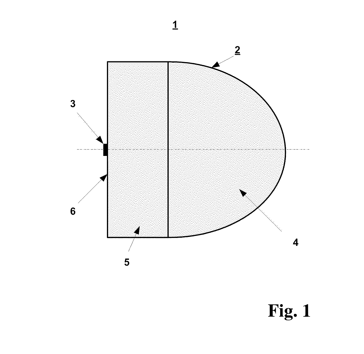
[0048]According to the invention, it is provided an increased gain value in lens antennas having large diameters (over 10×-20× wavelength in free space, which is required for use in radio-relay millimeter wave point-to-point communications). An example of a lens antenna 200 according to one of the embodiments is shown in FIG. 3. The antenna 200 comprises a lens 10 and an antenna element 20, which is a primary antenna element. The lens 10 consists of a collimating part 11 and an extension part 12. The part 11 is integrally formed with the part 12, and the parts 11 and 12 of the lens 10 are made of a dielectric material. The antenna element 20 is formed by a hollow waveguide 21 with a transition segment 23 between the input aperture and the radiating opening facing the lens, said radiating opening having width Wae and comprising a dielectric insert 22. The part 12 of the lens 10 comprises a substantially flat surface 13, and the antenna element 20 is rigidly fixed on the surface 13 by...


PUM


Abstract

Disclosed is a lens antenna comprising a dielectric lens consisting of a collimating part and an extension part, and an antenna element. The extension part of the lens comprises a substantially flat surface crossed by the axis of the collimating part, and the antenna element is rigidly fixed on the surface. The antenna element is formed by a hollow waveguide and comprises a dielectric insert with one end thereof adjacent to said surface; the size of the radiating opening of the waveguide is determined by the predefined width of the main beam and by side lobe levels of the radiation pattern of the lens antenna. The technical result of the invention is an increase in realized gain value due to the use of a waveguide antenna element with a dielectric insert, which provides impedance matching in a wide frequency bandwidth. The present invention can be used in radio-relay point-to-point communication systems, e.g. for forming backhaul networks of cellular mobile communication, in car radars and other radars, in microwave RF tags, in local and personal communication systems, in satellite and intersatellite communication systems, etc.

Description

CROSS-REFERENCE[0001]The present application is continuation of PCT / RU2013 / 000429 filed on May 27, 2013, entitled “LENS ANTENNA”, the entirety of which is incorporated herein by reference.FIELD OF THE INVENTION[0002]The present invention relates to antenna engineering, more particularly to novel lens antennas used in various applications of millimeter wave radio communication systems, such as radio-relay point-to-point communication systems and backhaul networks of mobile cellular communications, radars, satellite and intersatellite communication systems, local and personal communication systems, etc.BACKGROUND ART[0003]The demand for data throughput growth leads to increasingly widespread use of various radio communication systems operating in the millimeter wave range. Such increase is associated, on the one hand, with a wide frequency bandwidth available for use in said range, and on the other hand, with significant technological advances made over the past few decades, allowing ...

Claims


Application Information

Patent Timeline
IPC IPC(8): H01Q19/06H01Q13/00H01Q15/08H01Q21/29
CPCH01Q19/062H01Q13/00H01Q21/29H01Q15/08
Inventor ARTEMENKO, ALEKSEY, ANDREEVICHMOZHAROVSKIY, ANDREY, VIKTOROVICHSSORIN, VLADIMIR, NIKOLAEVICHSEVAST'YANOV, ALEKSEY, GENNAD'EVICHMASLENNIKOV, ROMAN, OLEGOVICH
Owner OBSHCHESTVO S OGRANICHENNOJ OTVETSTVENNOSTYU RADIO GIGABIT
Why Eureka
Try Eureka