Method and apparatus for antenna tuning

a technology of antenna impedance matching and antenna, applied in the field of wireless communication, can solve the problems of increasing mismatch between current and voltage, and the phase difference between current and voltage also corresponds to a greater mismatch, so as to reduce the deviation and reduce the mismatch

Active Publication Date: 2011-04-14
TEXAS INSTR INC
View PDF3 Cites 190 Cited by
  • Summary
  • Abstract
  • Description
  • Claims
  • Application Information

AI Technical Summary

Benefits of technology

[0011]The present invention also provides a transmitter having one or more tunable circuit elements and an associated antenna. The transmitter has a power amplifier driver, the output of which is coupled to the input of a power amplifier through an optional matching network. The output of the power amplifier is coupled to the antenna. A detector is configured to sense a load current of either the power amplifier driver or the power amplifier, or of both, and the detector is also configured to generate an error signal that indicates a deviation of the load current from a predetermined value. The error signal is sent to a controller that calculates a correction based on the error signal, and that adjusts one or more parameters of the tunable...

Problems solved by technology

These load currents are indicators of how efficient the coupling is to the next stage or antenna, in that higher amplitude drive currents are required to achieve ...

Method used


Image

  • Method and apparatus for antenna tuning
  • Method and apparatus for antenna tuning
  • Method and apparatus for antenna tuning

Examples


first embodiment

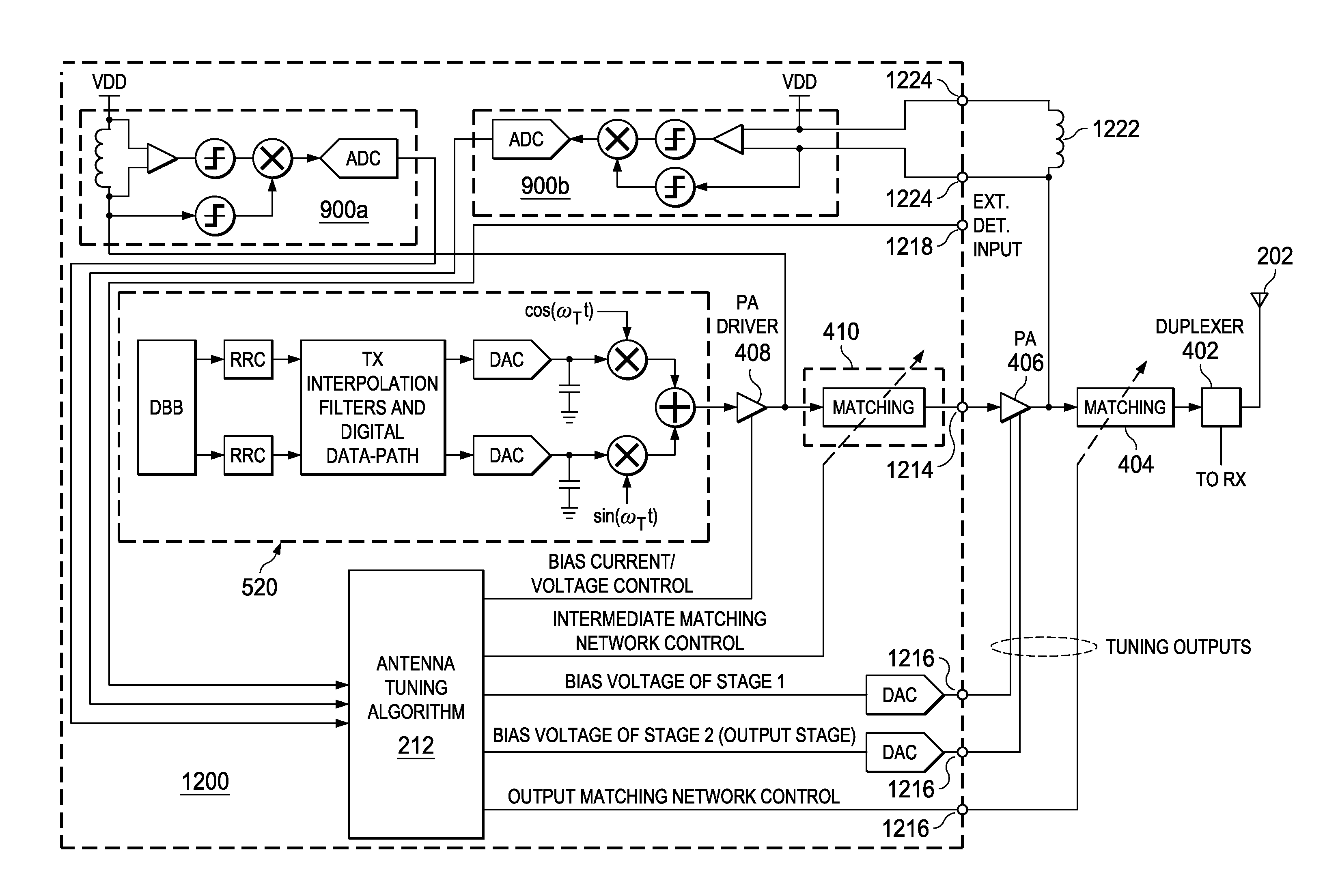
[0041]Referring to FIG. 5, a schematic diagram of an exemplary transmitter 500 with antenna tuning according to the present invention is shown. In this example, RF signals are generated for transmission by low-power RF circuitry in block 520. The illustrated circuit uses digital signal processing (DSP) technology to generate the analog RF signals presented to the input of power amplifier driver 408 in an example wideband code division multiple access (W-CDMA) system, although the present invention may be applied to many different types of wireless signals and systems. Digital baseband processor 522 generates two quadrature modulation outputs that are each filtered by root raised-cosine digital pulse shaping filters 524, further processed by transmit interpolation filters and associated DSP in block 526, followed by conversion from digital to analog by digital-to-analog converters (DACs) 528. The now-analog baseband modulation signals are mixed in mixers 530 with in-phase 532 and qua...

second embodiment

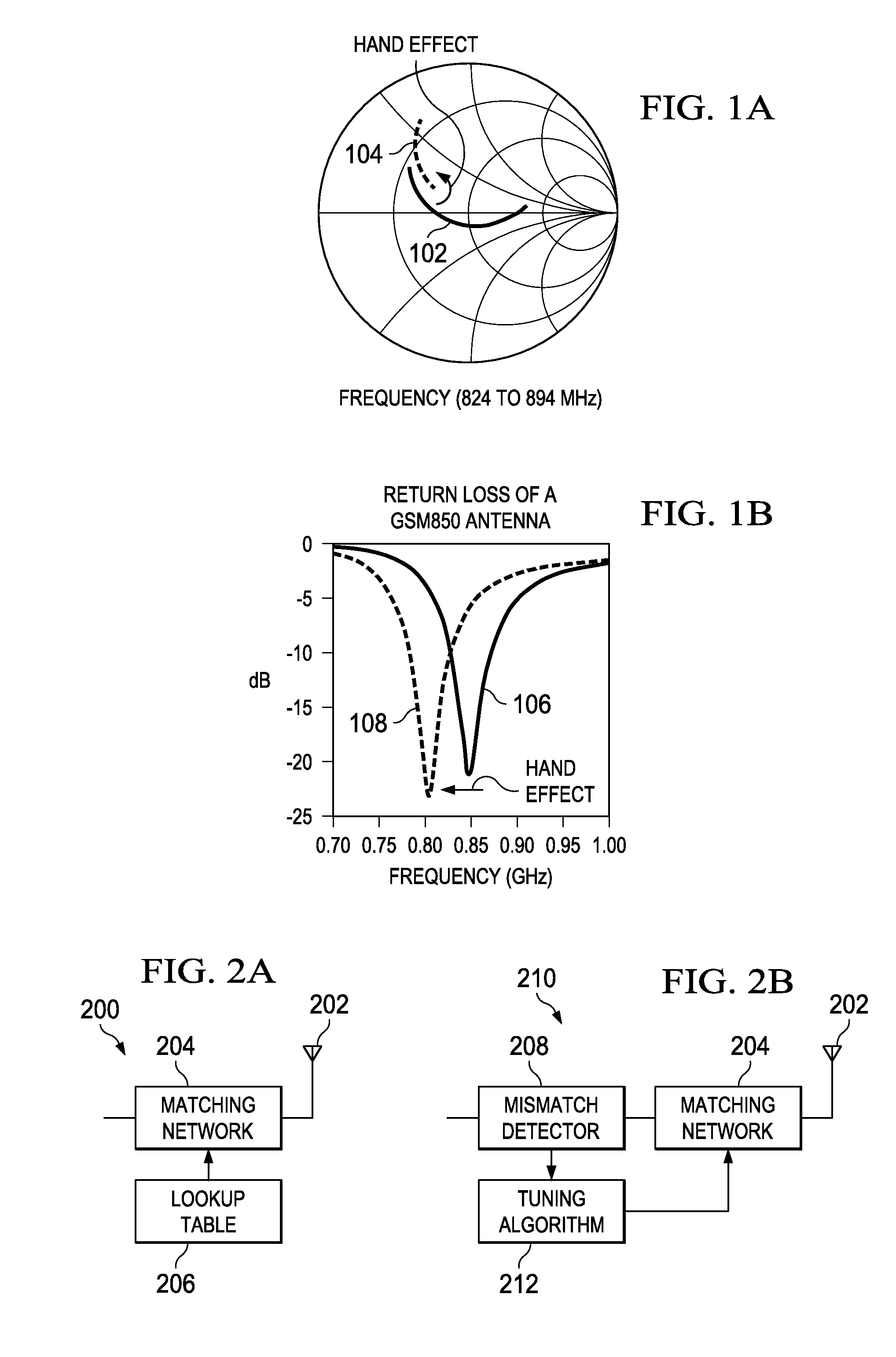
[0048]The reactive part of antenna impedance may change more in response to changes in environment than the resistive (real) part. Thus detecting a change in phase shift between RF voltage and current at the sensed node may provide a more sensitive response to changes in mismatch than sensing the signal amplitude. A second embodiment is next described using a detector circuit capable of generating an error signal based on the relative phase between voltage and current within the transmitter's antenna drive circuit.

[0049]Referring now to FIG. 8, a schematic diagram is shown of a transmitter 800 according to a second embodiment of the present invention. A detector 900 is shown that is capable of generating an error signal based on the relative phase between the RF voltage and current at node 808. To do so, a voltage difference is sensed across choke or inductor 802, where the voltage difference is developed in response to an RF load current flow from supply node 806 at voltage VDD to ...


PUM


Abstract

A method for tuning a transmitter in order to improve impedance matching to an antenna or to intermediate radio frequency stages uses an error detector that senses a deviation of the amplitude or phase angle of a load current of a power amplifier driver or of a power amplifier. A controller calculates a correction and dynamically adjusts tunable transmitter parameters, which may include values of components in matching networks or bias voltages in the power amplifier or the power amplifier driver, so as to reduce the deviation and thereby improve the impedance matching. The load current of the power amplifier may alternatively be sensed by measuring the duty cycle of its switching mode power supply. A transmitter having a power amplifier and one or more tunable circuit elements incorporates an error detector that senses the amplitude or phase of a load current and a controller that adjusts one or more tunable parameters to reduce impedance mismatch. An integrated circuit device suitable for use in a transmitter includes a power amplifier driver circuit and a detector circuit capable of sensing a load current, and a controller circuit that can adjust tunable parameters either within or external to the integrated circuit. By eliminating directional couplers and integrating the detectors and power amplifier drivers, the size, complexity, and cost of wireless transceivers can be reduced, while efficiency and power consumption are improved through the dynamic adjustment of operating points and impedance matching.

Description

BACKGROUND OF THE INVENTION[0001]1. Field of the Invention[0002]The present invention relates generally to the field of wireless communications, and more particularly, to a method and apparatus for antenna impedance matching in a wireless communication device.[0003]2. Description of the Related Art[0004]It is well known that impedance matching is required to optimize energy transfer from a source to a load in radio-frequency circuits. In radio communication devices such as wireless transceivers, there are several places within the system requiring impedance matching, but one of the most challenging is the connection between a transmitter as a source and an antenna as a load. A poor impedance match in this part of a transceiver system results in the inefficient transfer of power to the antenna, and thus requires more power, for example from a battery in a portable system, in order to achieve a given level of radiated power needed for a robust communication link. A similar situation o...

Claims


Application Information

Patent Timeline
IPC IPC(8): H04B1/04
CPCH04B1/0458H03J2200/06
Inventor MUHAMMAD, KHURRAM
Owner TEXAS INSTR INC
Why Eureka
Try Eureka