Antenna, method for manufacturing the antenna, and communication apparatus including the antenna

a technology for antennas and communication devices, applied in the direction of resonant antennas, antenna earthings, protection materials radiating elements, etc., can solve the problems of disturbance of the size of the wireless apparatus on which the antenna is mounted, and the difficulty of integrating components, so as to reduce the size of the rf circuit

Inactive Publication Date: 2005-05-12
HITACHI LTD +1
View PDF5 Cites 173 Cited by
  • Summary
  • Abstract
  • Description
  • Claims
  • Application Information

AI Technical Summary

Benefits of technology

[0013] If a feeding point can be shared by electromagnetic waves of different frequencies in a multimode antenna, RF circuits (transmission and reception circuits) using a plurality of frequencies can share one feeding point. Consequently, the semiconductor integrated circuit technique can be applied to integrate the RF circuit section. Thus, the size the RF circuit can be redu...

Problems solved by technology

Consequently, it is difficult to integrate those components and reductio...

Method used


Image

  • Antenna, method for manufacturing the antenna, and communication apparatus including the antenna
  • Antenna, method for manufacturing the antenna, and communication apparatus including the antenna
  • Antenna, method for manufacturing the antenna, and communication apparatus including the antenna

Examples


first embodiment

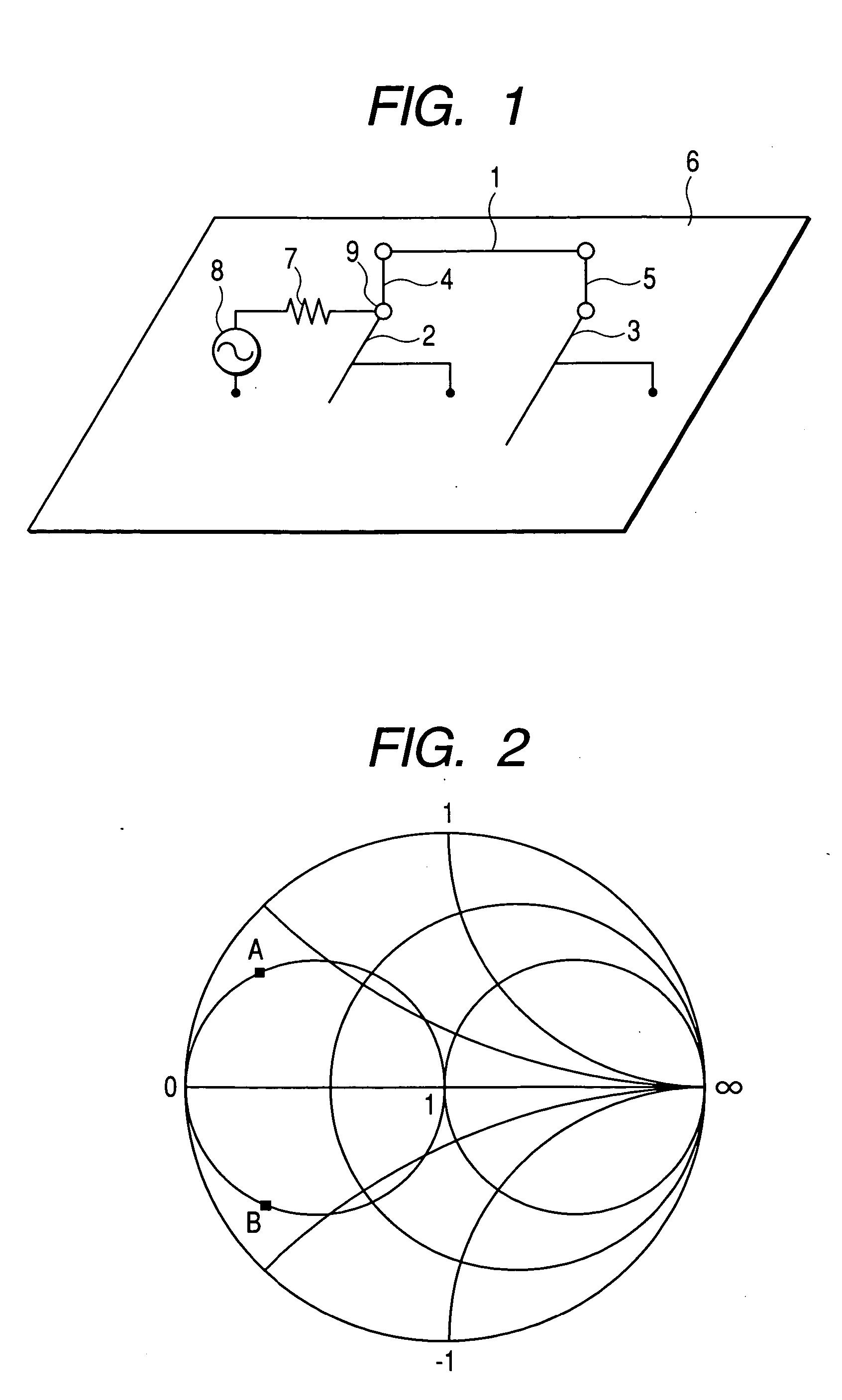
[0036] the invention will be described with reference to FIGS. 1 and 2. FIG. 1 is a diagram showing components of an antenna of the invention and coupling relations of the components. FIG. 2 is a Smith chart illustrating the characteristics of the antenna of FIG. 1.

[0037] The embodiment shown in FIG. 1 employs the structure such that one end of a radiating conductor 1 and one end of a first connecting conductor 4 are coupled to each other, a wire conductor 2 having a first branch is connected between the other end of the first connecting conductor 4 and a ground (ground conductor) 6, the other end of the radiating conductor 1 and one end of a second connecting conductor 5 are coupled to each other, a wire conductor 3 having a second branch is connected between the other end of the second connecting conductor 5 and the ground 6, and a coupling point between the first connecting conductor 4 and the wire conductor 2 having the first branch is used as a feeding point 9. An external RF c...

second embodiment

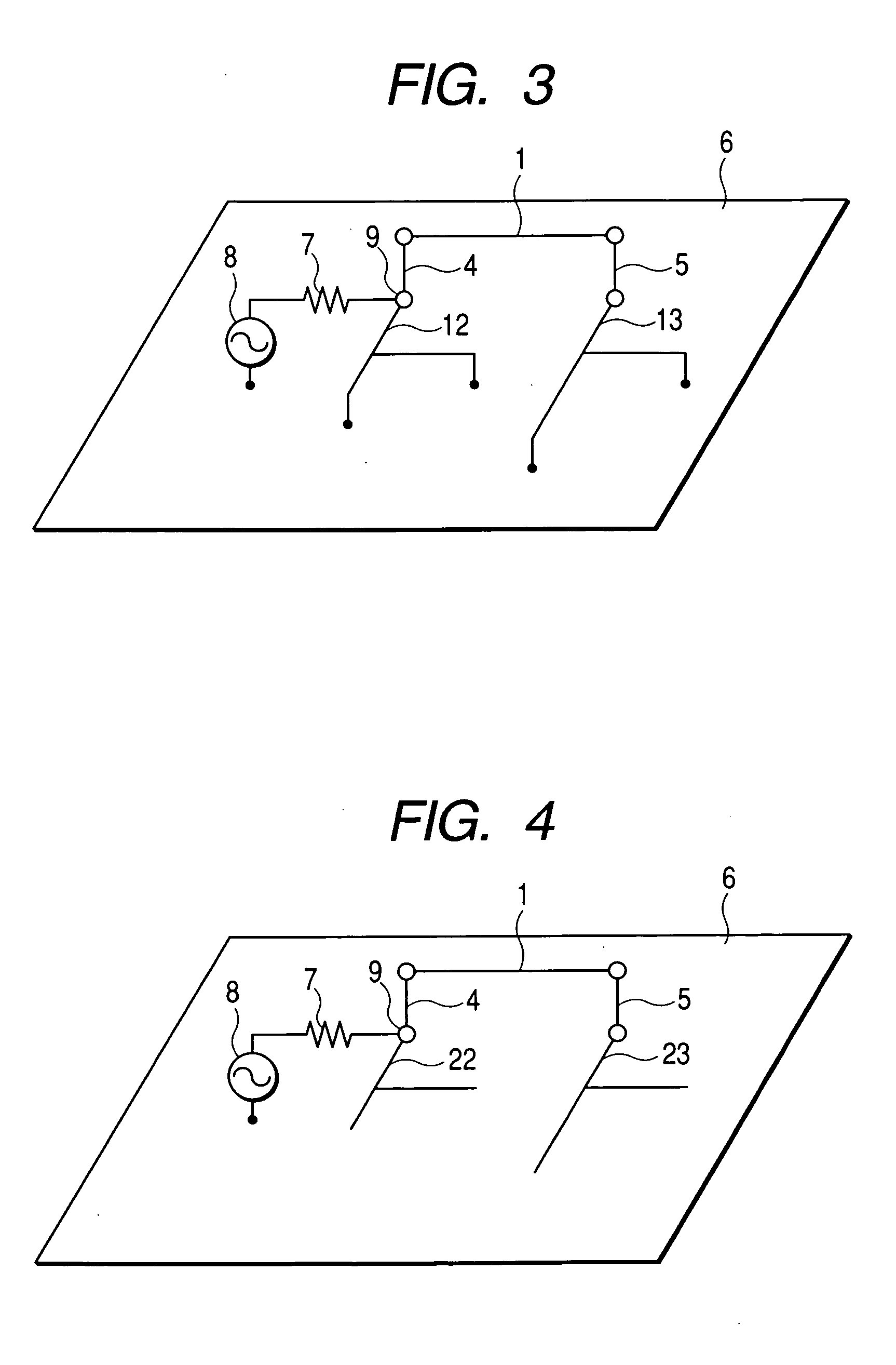
[0045] the invention will be described with reference to FIG. 3. FIG. 3 is a diagram showing components of an antenna according to the invention and the coupling relations of the components. The point different from the embodiment of FIG. 1 is that a wire conductor 12 having a first branch and a wire conductor 13 having a second branch are used in place of the wire conductor 2 having the first branch and the wire conductor 3 having the second branch. To the first branch of the wire conductor 12, a wire conductor whose one end is connected to the ground 6 and a wire conductor whose one end is similarly connected to the ground 6 are connected. To the second branch of the wire conductor 13, a wire conductor whose one end is connected to the ground 6 and a wire conductor whose one end is similarly connected to the ground 6 are connected.

[0046] The wire conductor 12 having the first branch and the wire conductor 13 having the second branch can be expressed by an equivalent circuit in whi...

third embodiment

[0047] the invention will be described by using FIG. 4. FIG. 4 is a diagram showing components of an antenna according to the invention and the coupling relations of the components. The point different from the embodiment of FIG. 1 is that a wire conductor 22 having a first branch and a wire conductor 23 having a second branch are used in place of the wire conductor 2 having the first branch and the wire conductor 3 having the second branch. Two wire conductors each having one open end are connected to the first branch of the wire conductor 22, and two wire conductors each having one open end are connected to the second branch of the wire conductor 23.

[0048] The wire conductor 22 having the first branch and the wire conductor 23 having the second branch can be expressed by an equivalent circuit in which two different open stubs are connected in parallel with the transmission line. Also in the embodiment, by setting the length of one open stub to the ½ wavelength at a frequency to wh...


PUM


Abstract

The invention provides a small multimode antenna capable of commonly using a single feeding point at a plurality of frequencies. The antenna includes a radiating conductor 1 disposed above a ground conductor 6 and distributed-constant circuits 2 and 3 coupled to the radiating conductor. Each of the distributed-constant circuits is constructed by a transmission line and has a branch. One end of the radiating conductor and one end of the distributed-constant circuit 2 are connected to each other to be a connection point and, further, the other end of the radiating conductor and one end of the distributed-constant circuit 3 are connected to each other. The connection point is a single feeding point 9 using the ground conductor as an earth. The distributed-constant circuits 2 and 3 are designed as an equivalent circuit in which different stubs are connected in parallel with a transmission line, and impedance matching at a plurality of frequencies is realized at the feeding point.

Description

CLAIM OF PRIORITY [0001] The present application claims priority from Japanese application JP 2003-382003 filed on Nov. 12, 2003, the content of which is hereby incorporated by reference into this application. FIELD OF THE INVENTION [0002] The present invention relates to an antenna of a wireless apparatus for providing multimedia services to the user. More particularly, the invention relates to a multimode antenna suitable for use in a multimedia wireless apparatus for providing plural services by information transmission using electromagnetic waves of different frequencies as media, a method for manufacturing the antenna, and a communication apparatus including the antenna. BACKGROUND OF THE INVENTION [0003] In recent years, multimedia services of various information provided by use of radio are becoming active, and a number of wireless apparatuses are developed and provided for practical use. The variety of services is being increased year after year to telephone, television, LAN...

Claims


Application Information

Patent Timeline
IPC IPC(8): H01Q1/22H01Q13/08H01Q1/24H01Q1/38H01Q1/40H01Q1/52H01Q5/10H01Q9/30H01Q9/42
CPCH01Q1/243H01Q9/30H01Q1/38
Inventor TAKEI, KENAOYAMA, HIROYUKI
Owner HITACHI LTD
Why Eureka
Try Eureka