Gas seal-in method for a bag with a gas filling compartment and packaging method for a bag with a gas filling compartment

a gas filling compartment and gas seal technology, which is applied in the direction of packaging, liquid handling, caps, etc., can solve the problems of bag being too flexible, deteriorating appearance, and problems such as arising

Active Publication Date: 2007-04-26
TOYO JIDOKI CO LTD
View PDF16 Cites 74 Cited by
  • Summary
  • Abstract
  • Description
  • Claims
  • Application Information

AI Technical Summary

Benefits of technology

[0009] Accordingly, it is an object of the present invention, which is devised in view of such problems as these, to make it possible, in packaging contents to be packaged using a bag with a ga

Problems solved by technology

With these bottom-gusseted type self-standing bags; however, when they are large in size or have a spout or the like attached at the bag mouth part, the bag will be too flexible, and problems will arise.
The upper part thereof bends over when the bag is displayed or used on a table, the appearance thereof deteriorates, or the self-standing properties thereof are lost so that it topples over.
Other problems are that it will be difficult to pour contents f

Method used


Image

  • Gas seal-in method for a bag with a gas filling compartment and packaging method for a bag with a gas filling compartment
  • Gas seal-in method for a bag with a gas filling compartment and packaging method for a bag with a gas filling compartment
  • Gas seal-in method for a bag with a gas filling compartment and packaging method for a bag with a gas filling compartment

Examples


Embodiment Construction

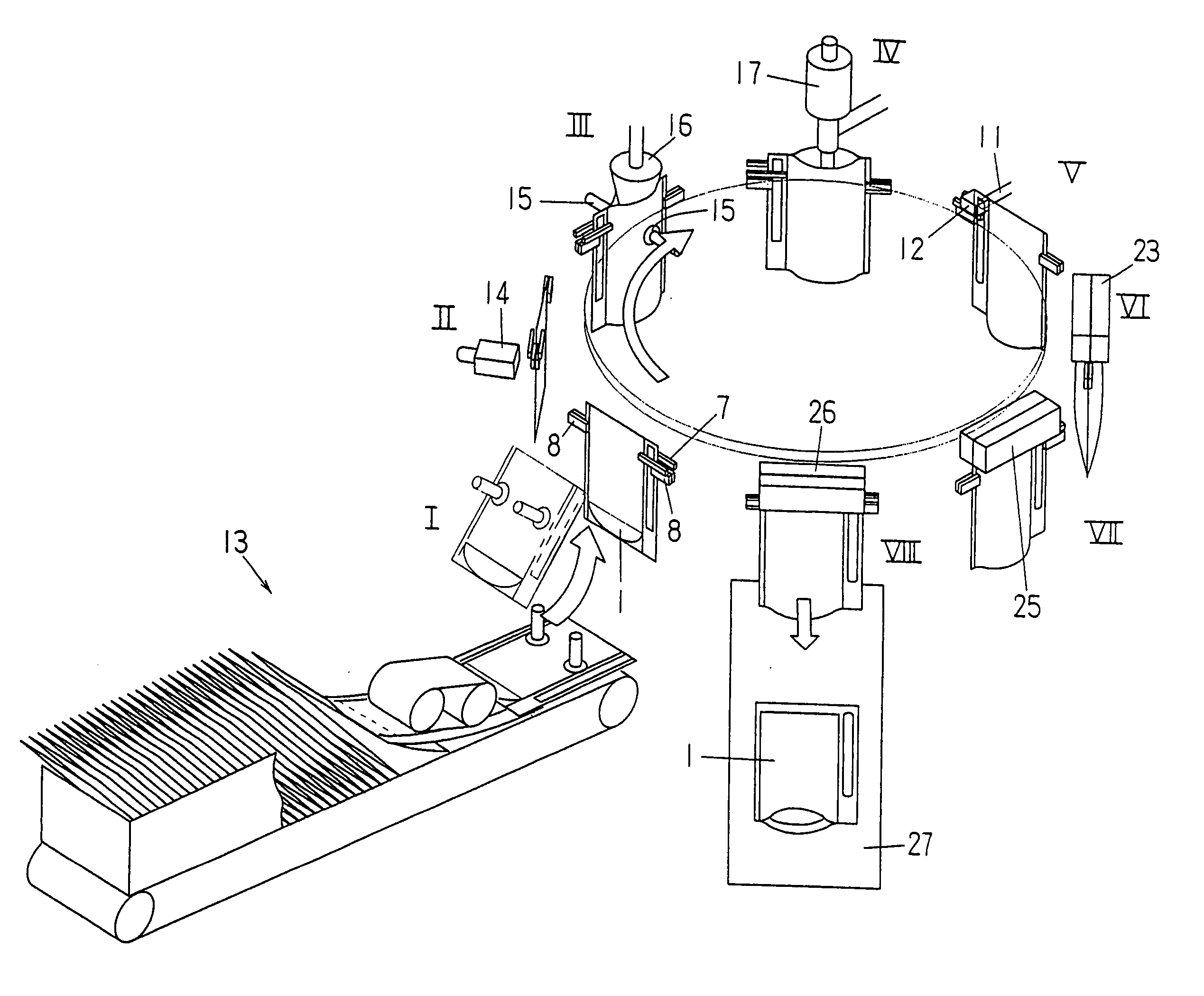
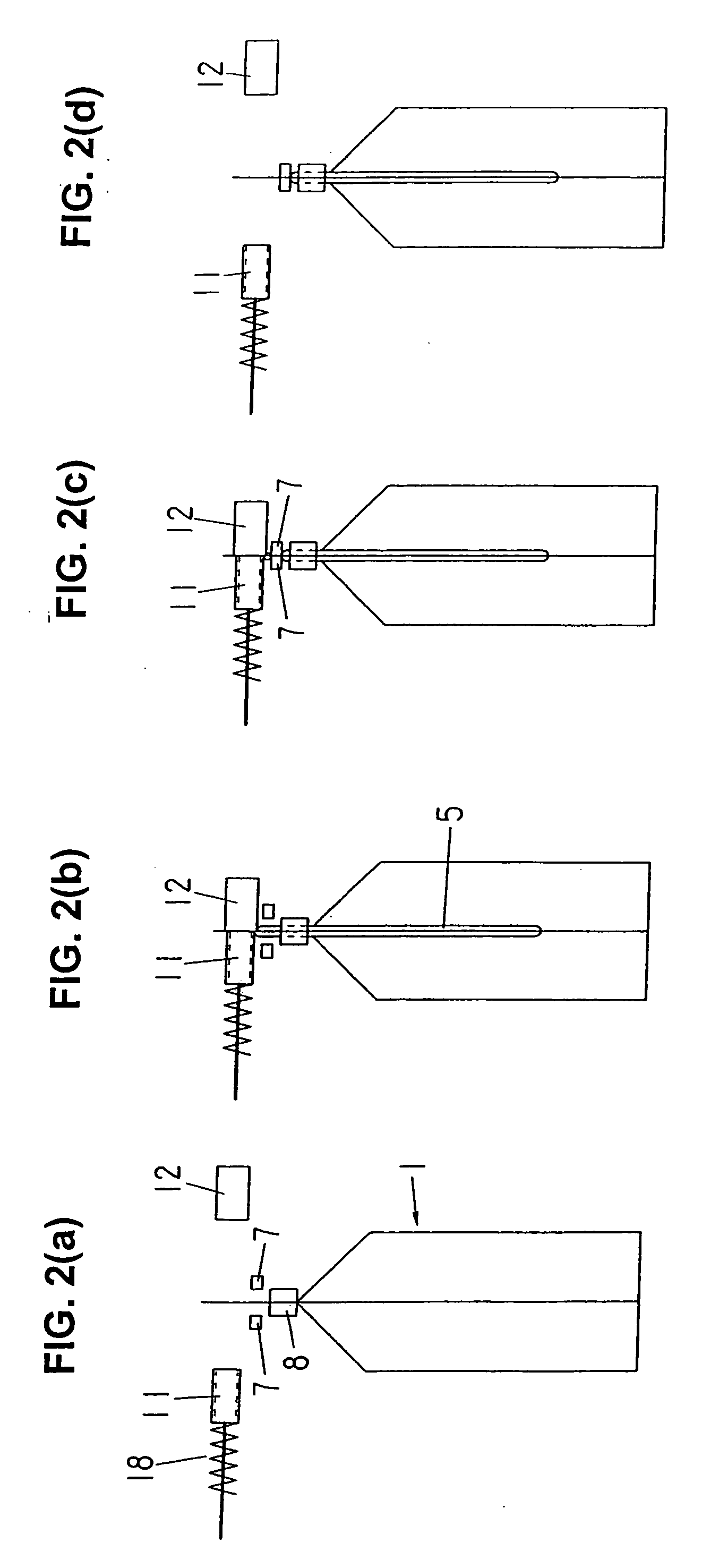
[0047] The present invention is now described below specifically with reference to FIG. 1 to 16.

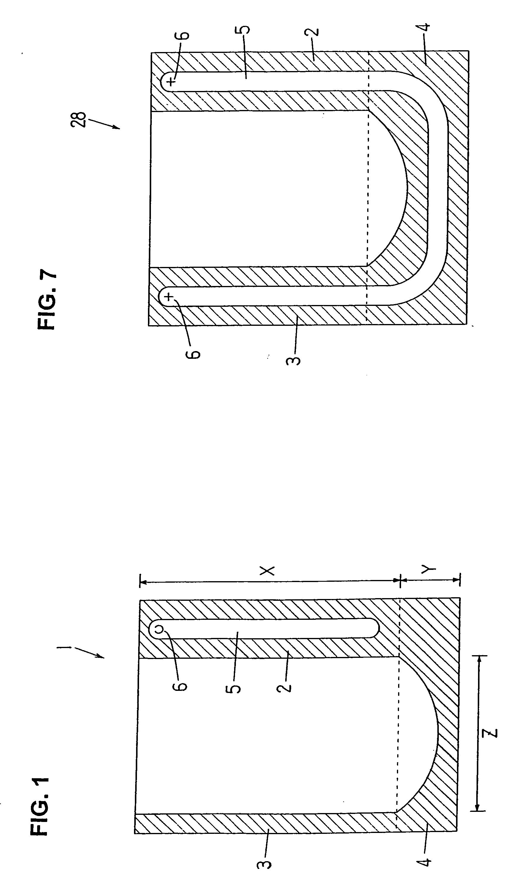
[0048] A bag with a gas filling compartment I of the present invention is shown in FIG. 1. The bag 1 is a bottom-gusseted type self-standing bag comprising front and back side films and folded bottom part films. In the lateral side edge area X of the bag 1, the front and back side films of the bag are bonded together; at the lateral side edge area Y, the front and back side films are bonded sandwiching the bottom part films (with the bottom part films themselves bonded together on the inside where folded); at the bottom part area Z the front and back side films are bonded respectively to the bottom part films (with the bottom part films not bonded to each other); at the upper edge, the front and back side films are not bonded, resulting in an open bag mouth. The sealed portions 2 and 3 in the two lateral side edge areas X and the sealed portion 4 in the side part area Y and bottom part a...


PUM

PropertyMeasurementUnit
Flow rateaaaaaaaaaa

Abstract

A method for sealing-in a gas in a gas filling compartment 5 of a bag having a cut-in 6 formed near the upper edge of the gas filling compartment. In the method, two edges of the bag with the contents inserted therein are gripped by grippers and suspended, the blow-in port of a gas (air) blow-in nozzle is brought to contact the cut-in, the back surface side of the bag is supported by a backing member, gas (air) is blown into the gas filling compartment, and the position below the cut-in is held from both sides of the bag by a gas cut-off grippers while the gas blow-in continues, so that the gas inside the gas filling compartment is not allowed to escape from the cut-in, and then the entire bag mouth, including the cut-in, is sealed.

Description

BACKGROUND OF THE INVENTION [0001] 1. Field of the Invention [0002] The present invention relates to a bag provided with a gas filling compartment for enhancing the shape retention and autonomy of the bag and protecting the contents packaged from shock or the like and more particularly to a method for sealing a gas into the gas filling compartment and further to a packaging method comprising for bag having a gas filling compartment that includes a process for sealing a gas into a gas filling compartment. [0003] 2. Description of the Related Art [0004] A self-standing bag (standing pouch) is a bag that exhibits enhanced self-standing properties, innovations having been made in the shape of the bottom surface or the shapes of the bottom surface and the side surfaces thereof. Bottom-gusseted type self-standing bags manufactured such that another folded film (bottom member) is sandwiched in the bottom part of the front and back films (trunk member), and the two lateral side edge parts a...

Claims


Application Information

Patent Timeline
IPC IPC(8): B65B31/00B65B1/04
CPCB31B2219/23B65B43/465B65B55/20B65B61/00B31B70/008
Inventor YASUHIRA, MASANORI
Owner TOYO JIDOKI CO LTD
Why Eureka
Try Eureka