Plasma treatment apparatus

a technology of treatment apparatus and plasma, which is applied in the direction of moving filter element filter, filtration separation, separation process, etc., can solve the problems of imbalance in the amount of gas supplied, difficult manufacturing and disassembly of the container, and a lot of labor and tim

Inactive Publication Date: 2007-04-26
MITSUBISHI HEAVY IND LTD
View PDF6 Cites 10 Cited by
  • Summary
  • Abstract
  • Description
  • Claims
  • Application Information

AI Technical Summary

Problems solved by technology

As a result, the piping system is complicated, making the configuration of the container complicated, eventually making the manufacture and disassembly of the container difficult.
To prevent gas leakage, etc. under these circumstances, much labor and a plenty of time have been required in inspecting the weld zone of the piping or testing for connection of the piping system.
Depending on individual differences of the pipings, the gas flow rate or the pressure loss differs, and may cause imbalances in the amounts of the gases supplied.

Method used


Image

  • Plasma treatment apparatus
  • Plasma treatment apparatus
  • Plasma treatment apparatus

Examples


Embodiment Construction

[0036] Embodiments of the present invention will now be described in detail with reference to the accompanying drawings, which in no way limit the invention.

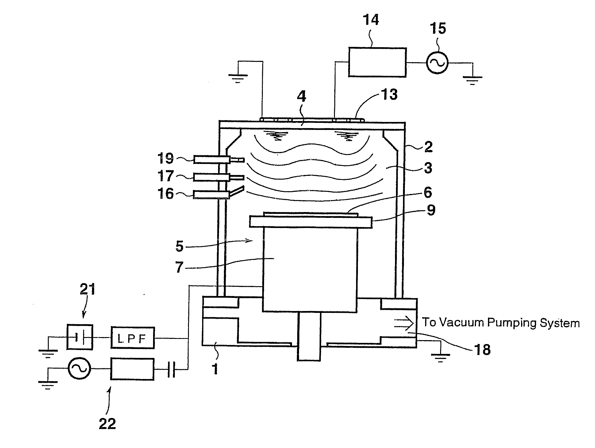
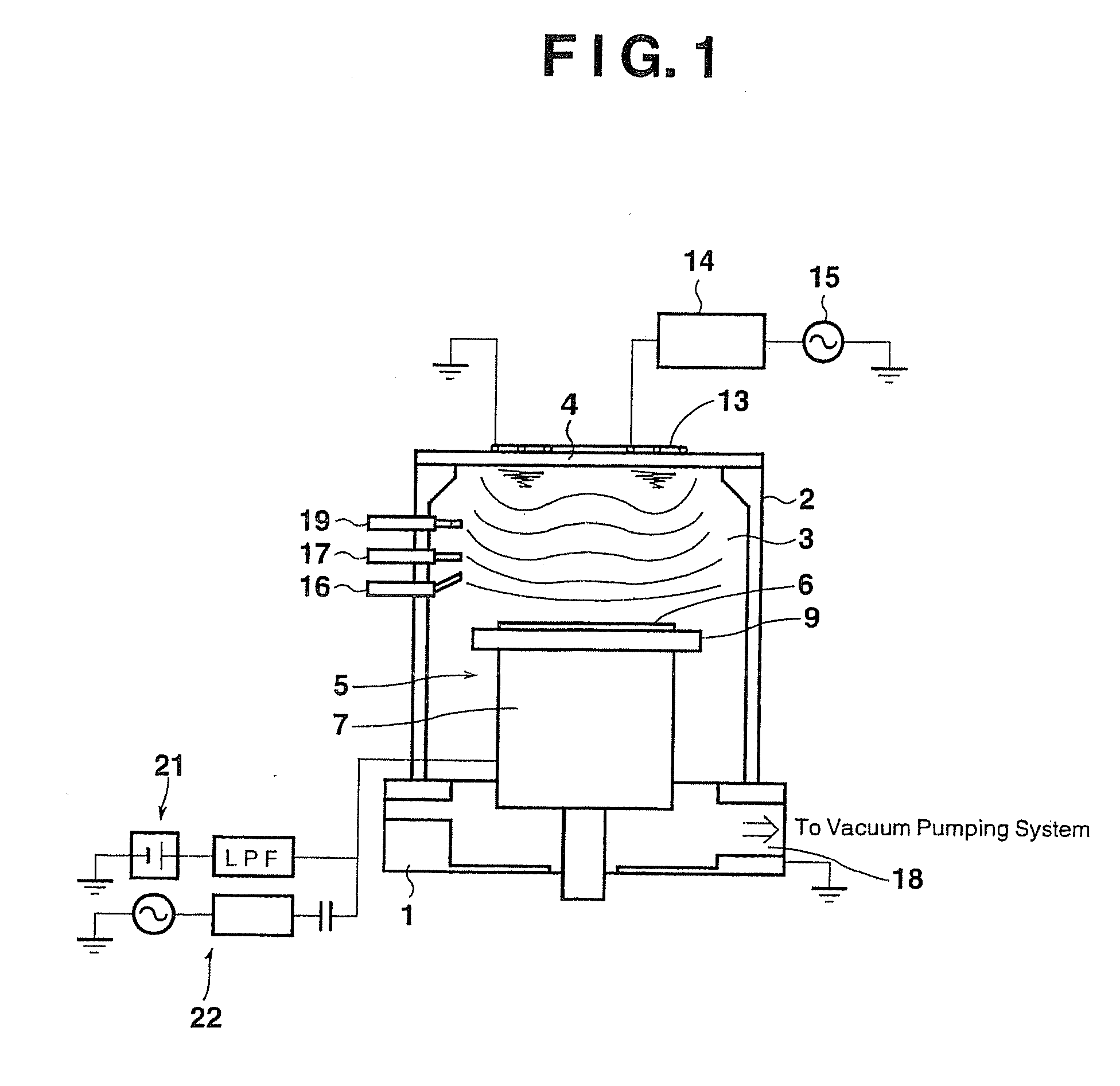
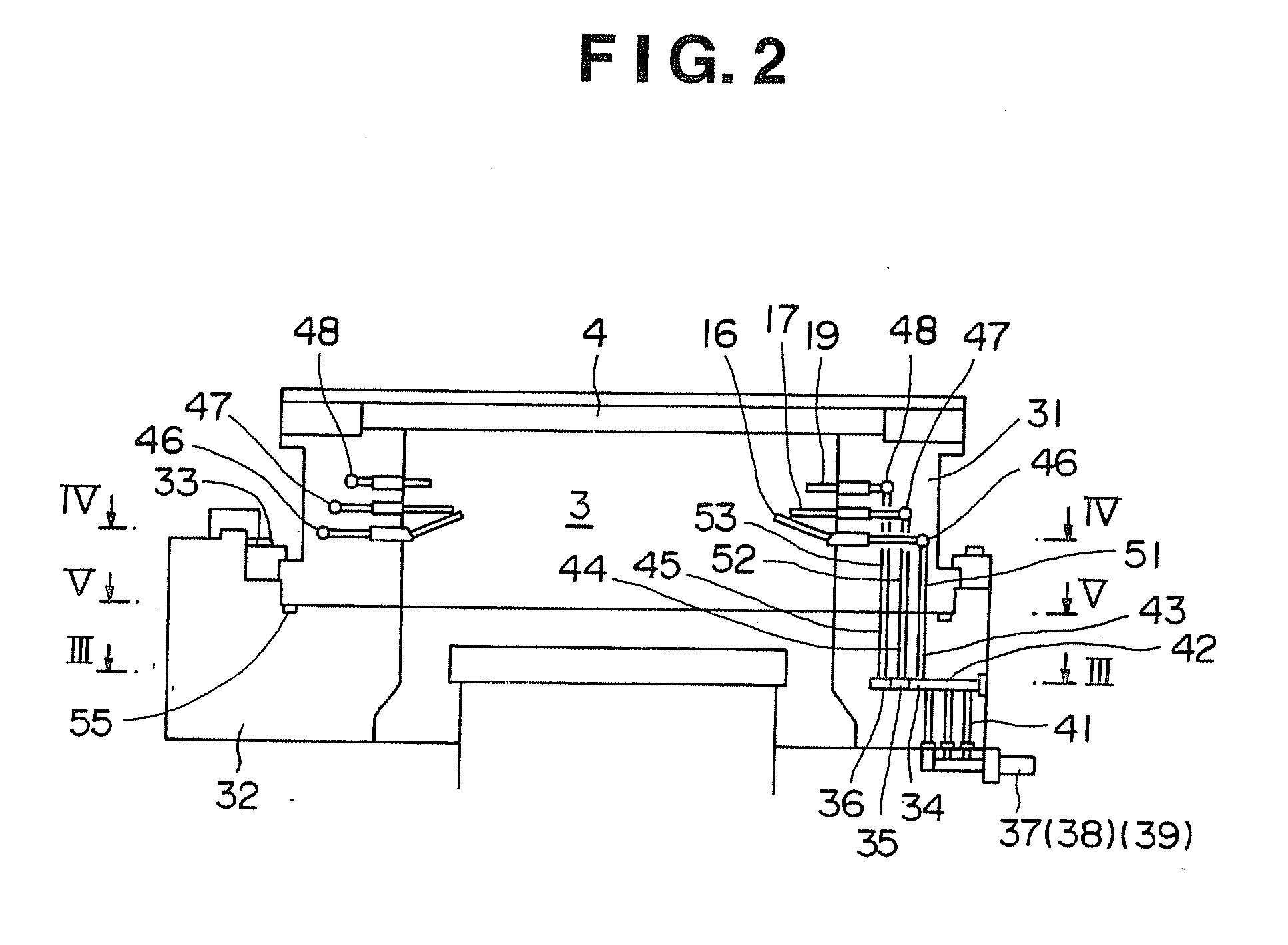
[0037]FIG. 1 is a schematic side view of a plasma CVD apparatus according to an embodiment of the present invention. FIG. 2 is a sectional view of essential parts of a container showing the concrete situation of gas pipings. FIG. 3 is a view taken along line III-III of FIG. 2. FIG. 4 is a view taken along line IV-IV of FIG. 2. FIG. 5 is a view taken along line V-V of FIG. 2. FIG. 6 is a conceptual view showing the situation of connection of the gas pipings.

[0038] As shown in FIG. 1, a cylindrical aluminum container 2 is provided on a base 1, and a film formation chamber 3 as a treatment chamber is defined within the container 2. A circular RF entrance window 4 is provided at the top of the container 2. The film formation chamber 3 at the center of the container 2 is equipped with a support stand device 5. The support stand dev...


PUM

PropertyMeasurementUnit
lengthaaaaaaaaaa
circumferenceaaaaaaaaaa
semiconductoraaaaaaaaaa

Abstract

A plasma CVD apparatus has a container, and channels composed of introduction grooves and circumferential grooves for different types of gases are formed within the container. The gases introduced through source gas piping, auxiliary gas piping, and cleaning gas piping are equally supplied to a plurality of supply nozzles, a plurality of auxiliary gas supply nozzles, and a plurality of cleaning gas nozzles. The configuration of the container can be simplified without complicating pipings for the gases.

Description

[0001] This application is a Divisional of co-pending application Ser. No. 10 / 636,590, filed on Aug. 8, 2003, the entire contents of which are hereby incorporated by reference and for which priority is claimed under 35 U.S.C. § 120. [0002] The entire disclosure of Japanese Patent Application No. 2002-232332 filed on Aug. 9, 2002, including specification, claims, drawings and summary, is incorporated herein by reference in its entirety.BACKGROUND OF THE INVENTION [0003] 1. Field of the Invention [0004] This invention relates to a plasma treatment apparatus for forming a film on the surface of a substrate by vapor deposition. [0005] 2. Description of the Related Art [0006] Currently, film formation using a plasma CVD (chemical vapor deposition) system is known for production of a semiconductor. The plasma CVD system is a system in which a source gas for constituting a film is introduced into a film formation chamber within a container, high frequency waves are shot from a high frequen...

Claims


Application Information

Patent Timeline
Patent Type & Authority Applications(United States)
IPC IPC(8): B01D33/70H05H1/46B01J19/08C23C16/00C23C16/44C23C16/455C23C16/50C23C16/507H01J37/32H01L21/205
CPCC23C16/455H01J37/3244C23C16/507C23C16/45563C23C16/00
Inventor YOSHIDA, KAZUTO
Owner MITSUBISHI HEAVY IND LTD
Why Eureka
Try Eureka