Displayed image capturing method and system

a technology of display image and capturing method, applied in the direction of exposure control, identification means, instruments, etc., can solve the problems of inability to apply a global shutter system, the capturing device cannot be placed at a desired position sufficiently apart from the screen, and the global shutter system is difficult to arrange the capturing device at a desired position from the screen, etc., to achieve the effect of suppressing the occurrence of flickers

Inactive Publication Date: 2007-04-26
OLYMPUS CORP
View PDF4 Cites 34 Cited by
  • Summary
  • Abstract
  • Description
  • Claims
  • Application Information

AI Technical Summary

Benefits of technology

[0029] Therefore, it is an object of the present invention to provide displayed image capturing method and system, wherein periodically renewed displayed images of the image display d

Problems solved by technology

However, when a displayed image of the image display device, which is periodically renewed, is to be captured, there would occur problems associated with the global shutter system.
However, in the capturing method disclosed in Japanese Patent Application Laid-open Publication No. 11-184,445, although it is possible to accurately adapt the exposure time to the image display device, the image display device and the capturing device must be connected to each other by a cable for transmitting the synchronizing signal, making it difficult to arrange the capturing device at a desired

Method used


Image

  • Displayed image capturing method and system
  • Displayed image capturing method and system
  • Displayed image capturing method and system

Examples


first embodiment

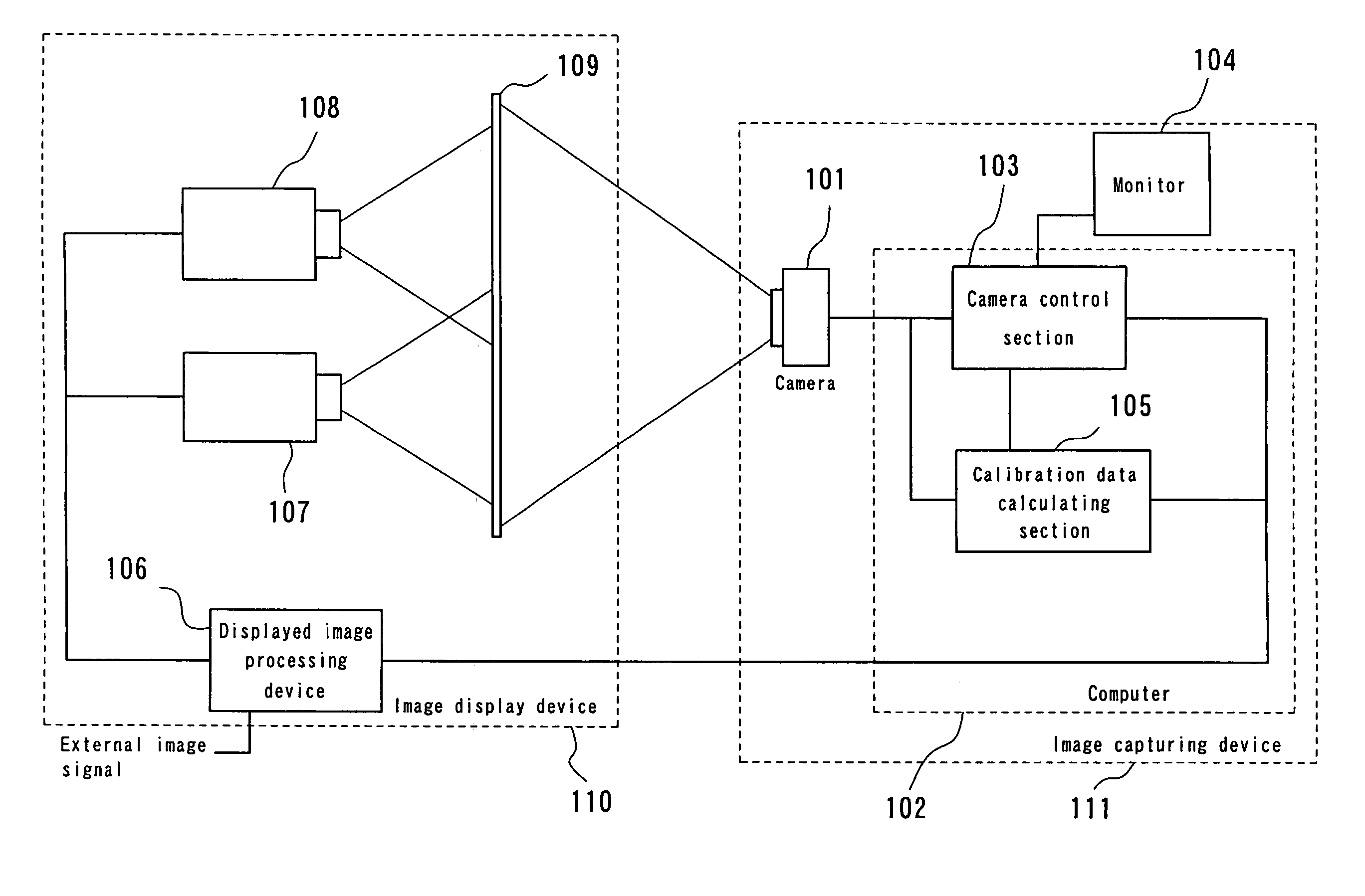
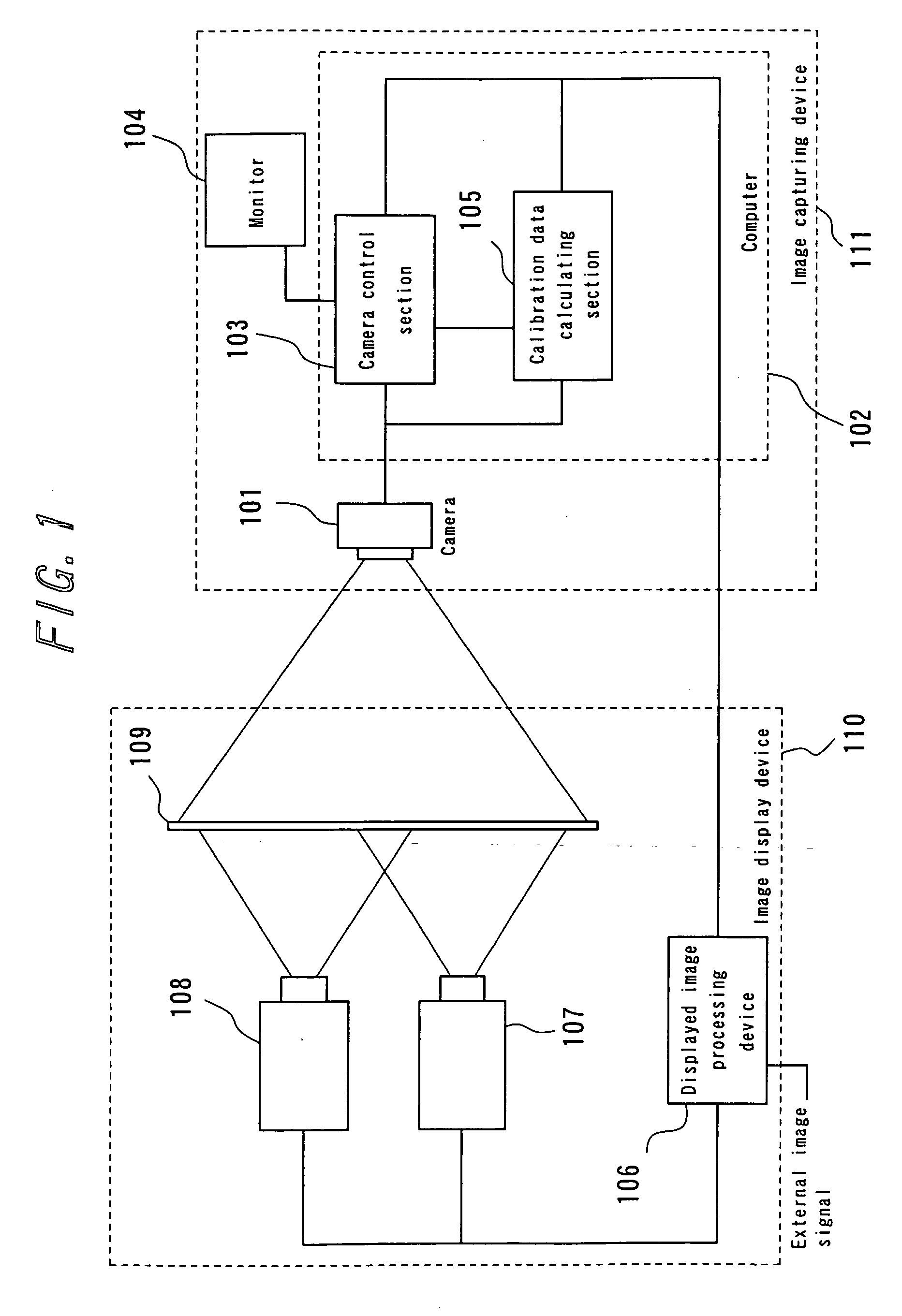
[0076] Referring to FIG. 1, there is shown a multi-projection system incorporating an image capturing system 111 according to a first embodiment of the present invention, wherein images displayed by an image display device 110 is captured by the capturing system 111. The image display device 110is in the form of a rear projector type multi-projection system comprising two projectors 107, 108 which are driven synchronously by an external synchronizing means, a displayed image processing device 106 for controlling the displayed image, such as distribution of the image to the two projectors 107, 108, and a screen 109 for displaying images projected from the projectors 107, 108.

[0077] The image capturing system 111 comprises a camera 101 for capturing the displayed image on the screen 109, a monitor 104 for monitoring the captured image, and a computer 102 with a camera control section 103 for controlling the exposure time of the camera, etc., and a calibration data calculating section...

second embodiment

[0126] A second embodiment of the present invention will be described below, wherein the two projectors 107, 108 are driven synchronously with each other by an internal synchronizing means, instead of an external synchronizing means as in the first embodiment. The following explanation is focused on the manner of calculating the flicker period and flicker amplitude.

[0127] In the case of multi-projectors operating with an internal synchronizing means, the displayed images are generally out of phase and the image renewal frequency tends to fluctuate due to individual differences. Therefore, if the displayed images of the multi-projectors are captured at once, it would be necessary to determine the synchronized exposure time that is optimum to the multi-projectors.

[0128] Schematically illustrated in FIGS. 9(a) to 9(c) is the capturing status of the images projected by two projectors which are operating synchronously with an internal synchronizing means. As shown in FIGS. 9(a) to 9(c)...


PUM


Abstract

A method for capturing displayed images periodically renewed and displayed on a display device, by a global-shutter type capturing device. Prior to actual capturing of the displayed images, a predetermined image is displayed on the display device and captured N-times (N>2) by the capturing device with a predetermined capturing period, and over an exposure time selected from a predetermined search range. Among the N captured images, there are calculated N−1 sum values or average values of differences between a specified image and remaining images at their predetermined regions. A flicker amplitude evaluation value is calculated based on a deviation of the sum values or the average values. A flickerless exposure time is calculated based on at least two exposure times, which are the minimal values among the flicker amplitude evaluation values corresponding to a plurality of exposure times within the search range. The exposure time of the capturing device is controlled based on the calculated flickerless exposure time, for actually capturing the displayed image of the display device.

Description

TECHNICAL FIELD [0001] The present invention relates to a method and a system for capturing displayed images which are displayed on an image display device. RELATED ART [0002] An image display device in the form of a multi-projection system is known, wherein a plurality of images are projected from corresponding projectors, and synthesized and displayed on a screen. In such a multi-projection system, for example, it is necessary to ensure that the difference in color and / or luminance between the images projected form the respective projectors, and the seams between the adjacent images are made as less noticeable as possible. [0003] Therefore, the applicant has proposed an image display device wherein a calibration image is projected onto a screen, the projected image is captured by a capturing means, such as a digital camera or the like, and various calibrations are performed based on the captured image. An image display device of this type is disclosed, for example, in Japanese Pat...

Claims


Application Information

Patent Timeline
IPC IPC(8): G03B7/00H04N5/235G09F9/00G09G5/00H04N5/335H04N5/351H04N5/353H04N5/357H04N5/372H04N5/378
CPCG03B21/26G03B21/53G03B37/04H04N5/2353H04N23/73
Inventor SASAKI, HIROSHI
Owner OLYMPUS CORP
Why Eureka
Try Eureka