Convex bicycle mirror

a bicycle mirror and convex technology, applied in the direction of bicycle mirrors, mirrors, instruments, etc., can solve the problems of limited safety of cyclists, cyclists losing focus, adding a possible danger to cyclists, etc., and achieve the effect of increasing safety for cyclists

Inactive Publication Date: 2007-04-26
VARNES BRYAN PAUL
View PDF2 Cites 10 Cited by
  • Summary
  • Abstract
  • Description
  • Claims
  • Application Information

AI Technical Summary

Benefits of technology

[0007] A mirror assembly of two convex-shaped mirrors is mounted to the fork, handle bars or frame of a bicycle, reflecting in the forward and / or behind direction of the rider. Each aforementioned mirror is multi-adjustable along its viewing axis for the best viewing requirement for the individual cyclist. The pronounced convex shape is comfortably viewed for increased safety for the cyclist from various riding positions. The forward or behind reflecting mirror can be removed from the stationary holder depending on the requirement of the cyclist.

Problems solved by technology

These mirrors are limited in their ability to provide safety for the cyclists mentioned above, particularly not when they are riding in the crouched or standing position.
While raising to the upright position and then looking behind himself, the cyclist loses focus on what may also be approaching or what is being approached, thereby adding a possible danger to the cyclist.
This also adds wind resistance to the cyclist, slowing him down.
This can create a blind spot to the cyclist or cause an illusion of the cyclist approaching objects or objects approaching from behind which do not exist.
This illusion could cause the cyclist to feel unsafe during the bike ride.
This can be a distraction to the cyclist's riding when he must constantly try to position his head in one location to be able to view with the device.
This limits the cyclist to a set position when riding and can cause added stress to his muscles.

Method used


Image

  • Convex bicycle mirror
  • Convex bicycle mirror

Examples


Embodiment Construction

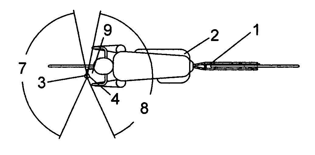
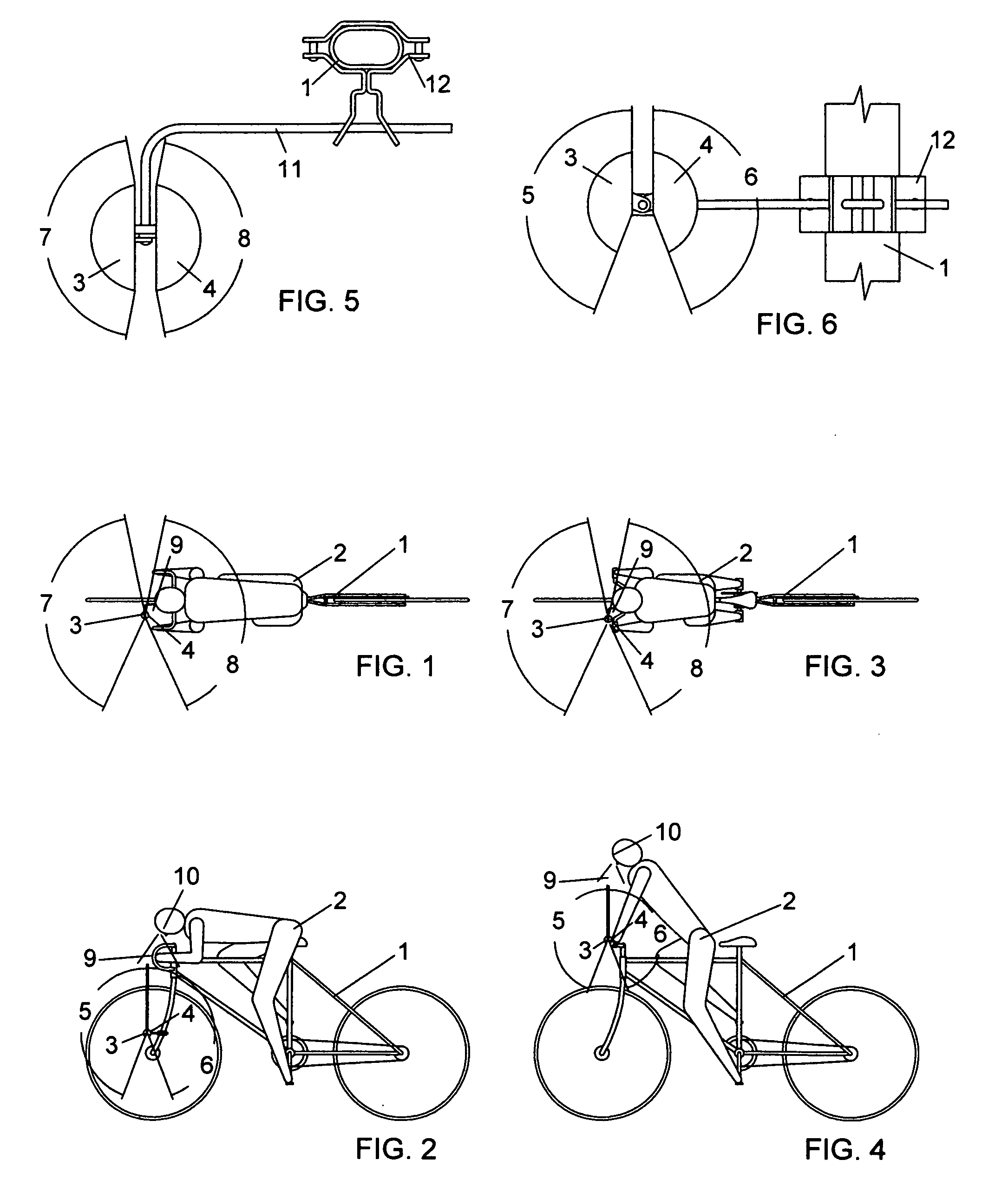
[0017] Shown in FIG. 1 is the top view of the standard type two-wheel bicycle 1 being ridden by the cyclist 2 with his body perpendicular to the bicycle and his face 10 pointed toward the ground in the crouched position. The cyclist 1, using his line of sight 9, to view the angle of reflection for an infinite distance 7 and 8 of the assembled convex mirrors 3 and 4 while riding.

[0018] Shown in FIG. 2 is the side view of the standard type two-wheel bicycle 1 being ridden by the cyclist 2 with his spine in a horizontal position and his face 10 pointed toward the ground in the crouched position. The cyclist 1 uses his line of sight 9, to view the angle of reflection for an infinite distance 5 and 6 of the assembled convex mirrors 3 and 4 while riding.

[0019] Shown in FIG. 3 is the top view of the standard type two-wheel bicycle 1 being ridden by the cyclist 2 with his body perpendicular to the bicycle, his buttocks removed from the seat and his spine in an upright position leaning for...


PUM


Abstract

Adjustable, multi-directional viewing, convex-shaped bicycle mirrors mounted as one assembly to the fork, handle bars or frame of a bicycle, reflecting in the forward and backward direction of the cyclist. When a cyclist is in the crouched riding position with his face pointed toward the ground for less wind resistance, the mirrors can be optically canvassed simultaneously, surveying in the forward direction for objects being approached and in the rear direction for objects approaching the cyclist. When attached to the bicycle to be closer to the bicyclist's face while he is riding in the standing position, the bicyclist can survey the forward preceding extent and/or backside approaching objects in the mirror while also negotiating diminutive objects upcoming on the ground.

Description

FIELD OF THE INVENTION [0001] This invention pertains to the safety of competitive-style bicycle riders who enjoy increased riding speeds over leisurely bike rides. BACKGROUND OF THE INVENTION [0002] Most patented bicycle mirrors are flat in design, attach to the bicycle's handle bars and can only be viewed to see approaching objects when riding in the upright position. The current mirror designs that attach to the bicycle and / or cyclist separately view either objects being approached or objects approaching. These mirrors are limited in their ability to provide safety for the cyclists mentioned above, particularly not when they are riding in the crouched or standing position. [0003] One current patent, U.S. Pat. No. 4,326,774 (Beigl), addresses this problem with a convex mirror attached to the fork of the bicycle but reflecting in the forward direction only. It does not reflect any backside approaching objects. The cyclist would still need to break from the crouched position, turnin...

Claims


Application Information

Patent Timeline
Patent Type & Authority Applications(United States)
IPC IPC(8): G02B5/08
CPCB62J29/00
Inventor VARNES, BRYAN PAUL
Owner VARNES BRYAN PAUL
Why Eureka
Try Eureka