Bifunctional LED headlamp

a technology of led headlamps and led modules, applied in the field of led headlamps, can solve the problems of large volume required for the packaging of led lighting modules and the additional space requirement of vehicles, and achieve the effect of convenient and efficient us

Inactive Publication Date: 2007-04-26
VARROC LIGHTING SYST SRO
View PDF45 Cites 23 Cited by
  • Summary
  • Abstract
  • Description
  • Claims
  • Application Information

AI Technical Summary

Benefits of technology

[0006] Consistent and consonant with the present invention, a headlamp for a vehicle wherein the headlamp facilitates an economic and an efficient use in both a low beam mode and a high beam mode, has surprisingly been discovered.

Problems solved by technology

Thus, a large volume is required to package the lighting modules.
This results in additional space requirements in a vehicle, which is undesirable.

Method used


Image

  • Bifunctional LED headlamp
  • Bifunctional LED headlamp
  • Bifunctional LED headlamp

Examples


Embodiment Construction

[0025] The following detailed description and appended drawings describe and illustrate various exemplary embodiments of the invention. The description and drawings serve to enable one skilled in the art to make and use the invention, and are not intended to limit the scope of the invention in any manner.

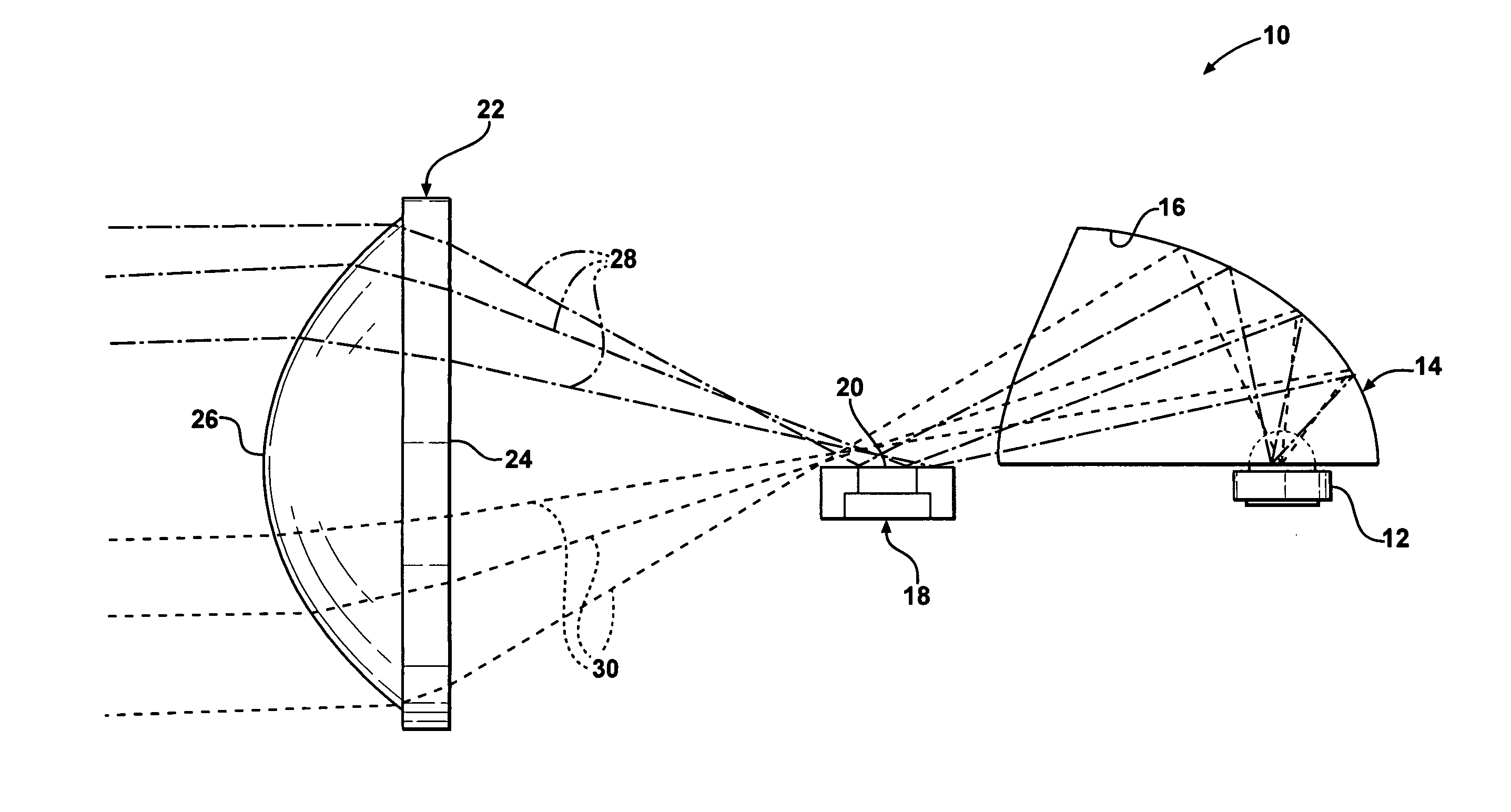
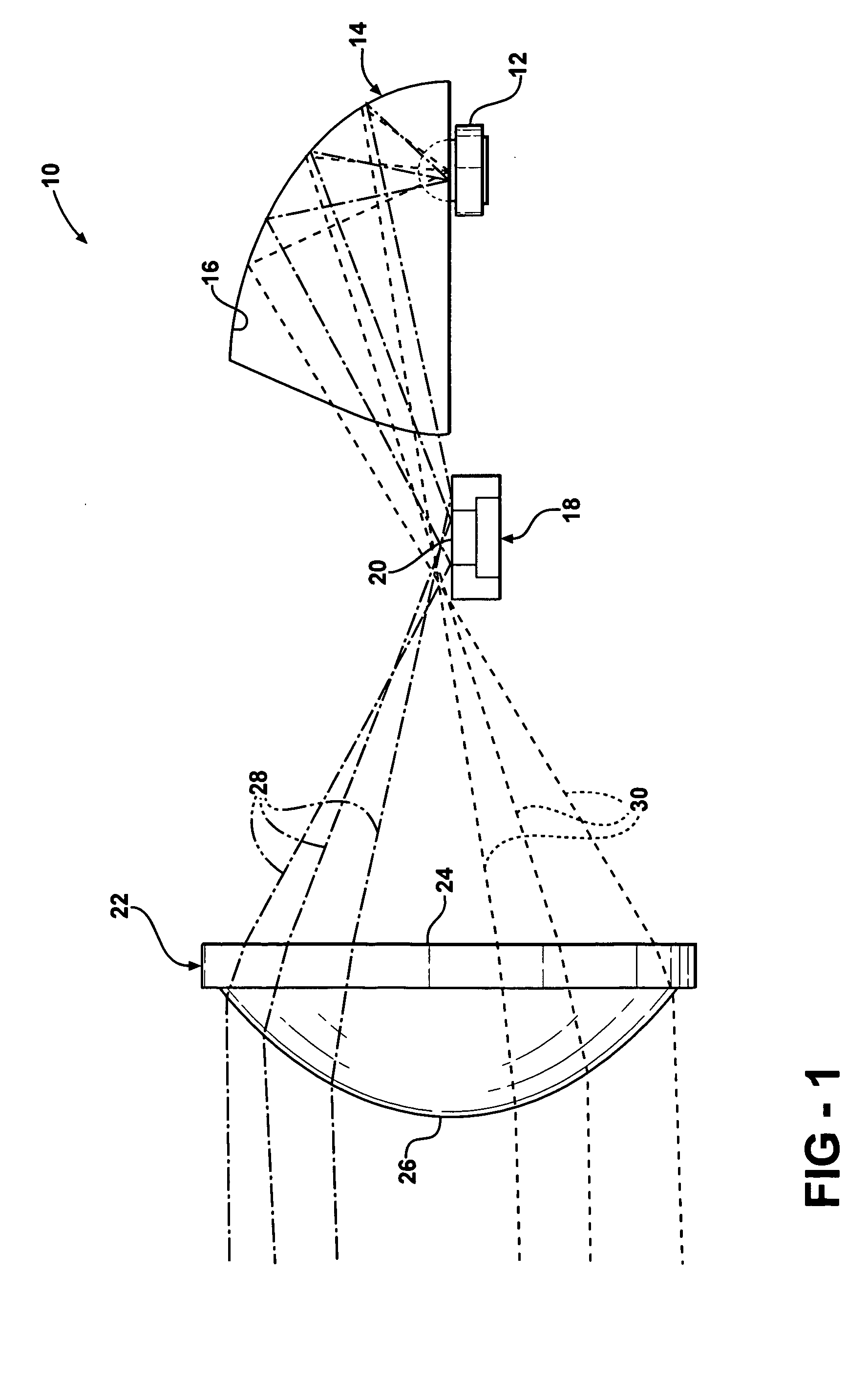
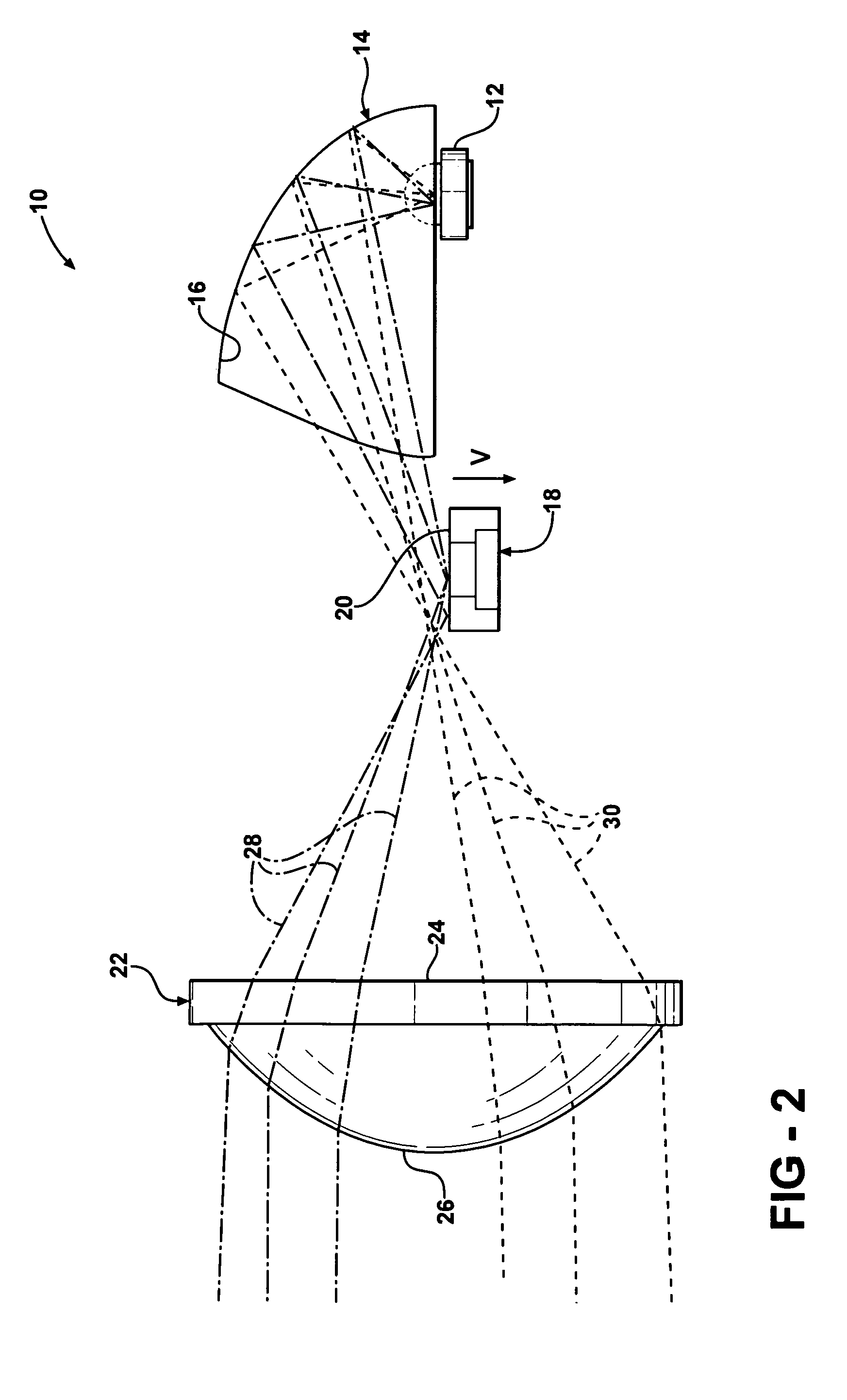
[0026]FIGS. 1-4 show a lighting module 10 of a projector-reflector type according to an embodiment of the invention. FIG. 1 shows the lighting module 10 in a low beam mode and FIGS. 2-4 show the lighting module 10 in a high beam mode. The module 10 includes a semiconductor light-emitting element 12 such as a light emitting diode (LED), for example. It is understood that additional light-emitting elements 12 can be used as desired. The light-emitting element 12 is connected to a source of electricity (not shown) and is disposed adjacent a reflector 14. In the embodiment shown, the reflector 14 is an ellipsoidal type, although other reflector types may be used as desired. An inner su...


PUM


Abstract

A bifunctional LED headlamp for a vehicle is disclosed, wherein at least one of a shield, a lens, a reflector, and an LED are movable to facilitate use of the headlamp in both a low beam mode and a high beam mode.

Description

FIELD OF THE INVENTION [0001] The invention relates to a lighting module and more particularly to a bifunctional LED headlamp for a vehicle, wherein the headlamp facilitates use in both a low beam mode and a high beam mode. BACKGROUND OF THE INVENTION [0002] Vehicle headlamps are required to include both a low beam mode and a high beam mode. Typically, the headlamp includes at least one light source and a reflector to direct light energy in a desired direction. [0003] More recently, light emitting diodes or LED's have been used as a light source in vehicle headlamps. Typically, a plurality of LED lighting modules is required to result in a desired light intensity. Thus, the headlamp may include a plurality of individual lighting modules having one or more LED light sources disposed therein. Additionally, each individual lighting module typically has a dedicated function such as beam spread, hot spot, or cut-off, for example. [0004] In prior art headlamps, to reach a desired intensit...

Claims


Application Information

Patent Timeline
Patent Type & Authority Applications(United States)
IPC IPC(8): F21V17/02
CPCF21S48/1159F21S48/1721F21S48/1742F21S48/1757F21V13/02F21Y2101/02F21S48/1388F21V7/0016F21V7/0033F21Y2115/10F21S41/143F21S41/148F21S41/153F21S41/255F21S41/285F21S41/321F21S41/323F21S41/365F21S41/43F21S41/60F21S41/635F21S41/657F21S41/675F21S41/683
Inventor EICHELBERGER, CHRIS L.LI, JOHN
Owner VARROC LIGHTING SYST SRO
Why Eureka
Try Eureka