

Method of providing a consistent preload on thrust bearings in a bearing assembly
- Summary
- Abstract
- Description
- Claims
- Application Information
AI Technical Summary
Benefits of technology
Problems solved by technology
Method used
Image

Examples
Embodiment Construction
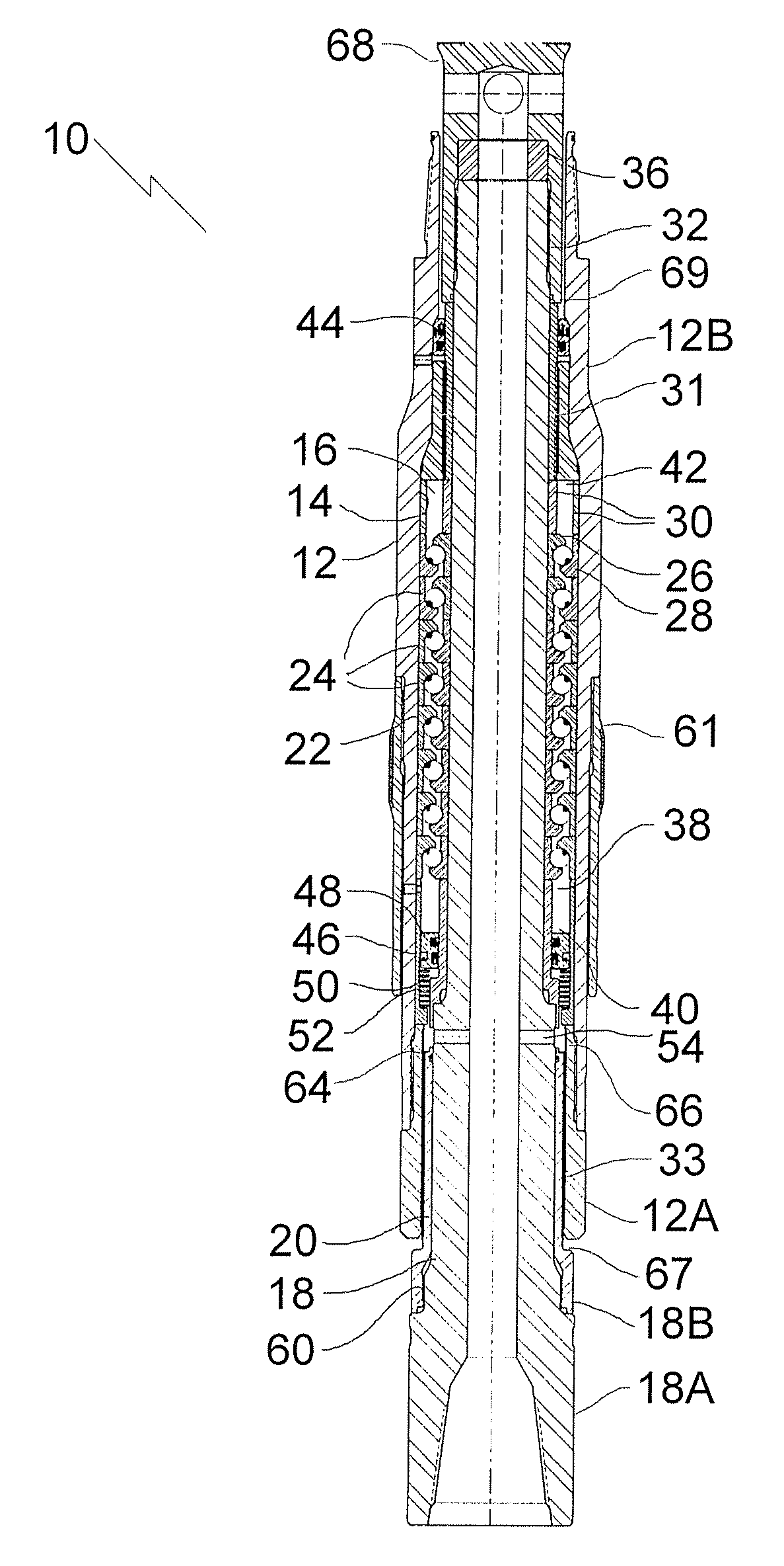
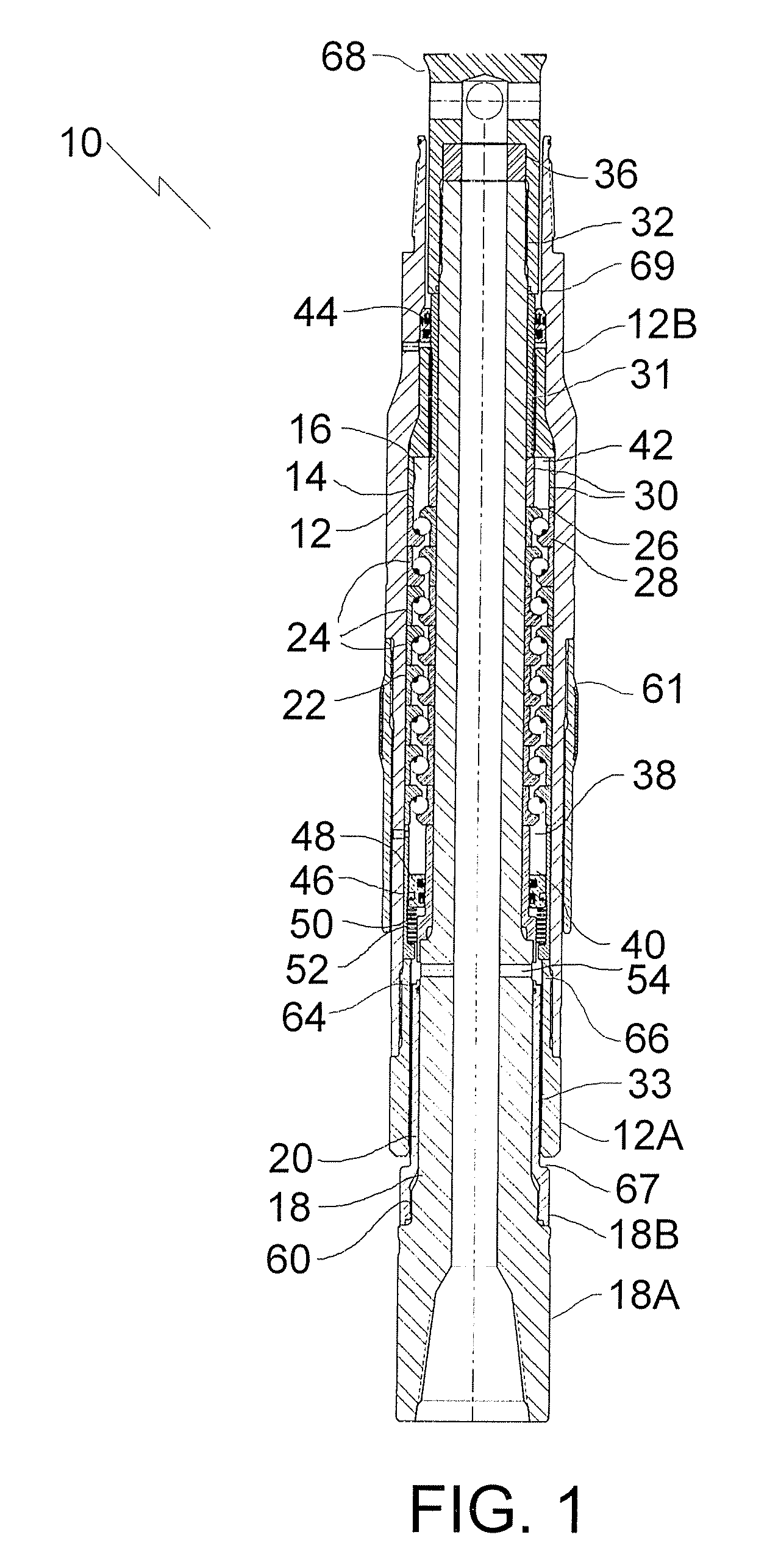
[0011] The preferred embodiment, a down hole bearing assembly generally identified by reference numeral 10, will now be described with reference to FIG. 1 through 6. There are several aspects of the present invention that will hereinafter be described.
Deformable Shims
[0012] Structure and Relationship of Parts:
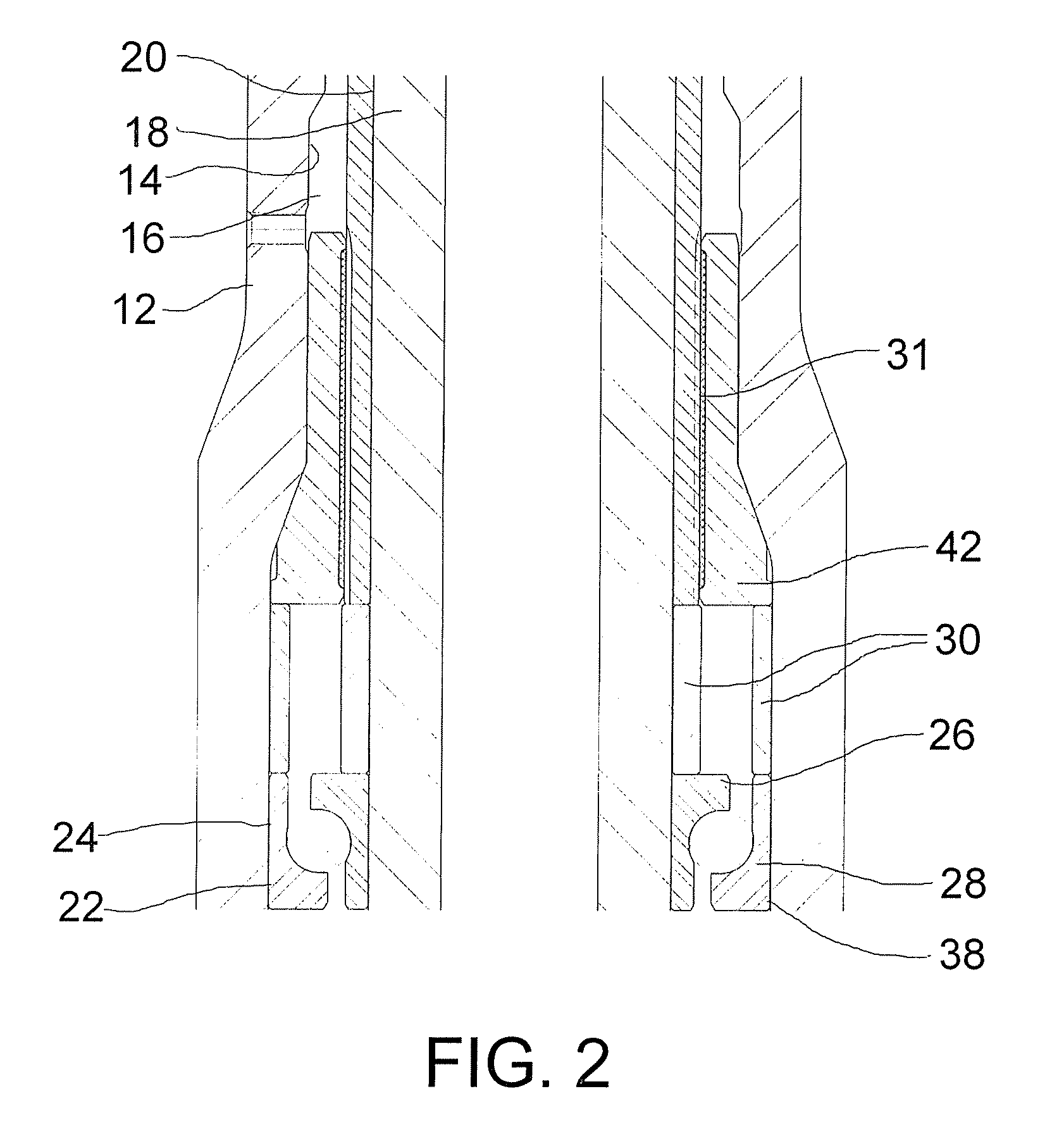
[0013] Referring now to FIG. 1, down hole bearing assembly 10 includes an outer housing 12 with an inner surface 14 defining an interior bore 16. An inner mandrel 18 is supported for rotation within interior bore 16 of outer housing 12. Inner mandrel 18 has an outer surface 20. A bearing stack 22 of thrust or radial bearings 24 is positioned between inner surface 14 of outer housing 12 and outer surface 20 of inner mandrel 18, where each thrust bearing 24 has an inner race 26 and an outer race 28. Referring to FIG. 2, deformable shims 30 are positioned against inner race 26 and outer race 28 of at least one of the thrust bearings 24 in bearing stack 22. Deformable shims 30 ...
PUM
 Abstract
Description
Claims
Application Information