Methods for manufacturing dental implant components

a technology for dental implants and components, applied in the field of dental implant systems, can solve the problem of less than accurate impression of the condition of the patient's mouth

Active Publication Date: 2007-04-26
BIOMET 3I LLC
View PDF99 Cites 127 Cited by
  • Summary
  • Abstract
  • Description
  • Claims
  • Application Information

AI Technical Summary

Benefits of technology

[0015] According to yet another process of the present invention, a method of manufacturing a rapid prototype overmold for locating a dental implant analog in a modified stone model for use in creating a tooth prosthesis is provided. The method installs a dental implant into a first installation site in bone having overlying gingiva in a mouth. An attachment member attaches to the dental implant. The attachment member has at least one informational marker for identifying physical characteristics of the attachment member. The process takes an impression of the mouth including the first installation site. The method prepares a stone model based on the impression. The stone model includes teeth models and model markers indicative of the at least one informational marker. The process scans the model. The scan of the model generates scan data. The scan data transfers to a graphical imaging software program. The process creates a three-dimensional image of the installation site. The method determines the model markers to gather information for manufacturing the custom-abutment. Custom-abutment dimensional information develops based on the three-dimensional image and the information gathered from the at least one informational marker. The custom-abutment dimensional information transfers to a milling machine. The milling machine fabricates the custom-abutment utilizing the cu

Problems solved by technology

Otherwise, a less than accurate impression of the condition of the patient's mouth is made.
Unfortunately, th

Method used


Image

  • Methods for manufacturing dental implant components
  • Methods for manufacturing dental implant components
  • Methods for manufacturing dental implant components

Examples


Embodiment Construction

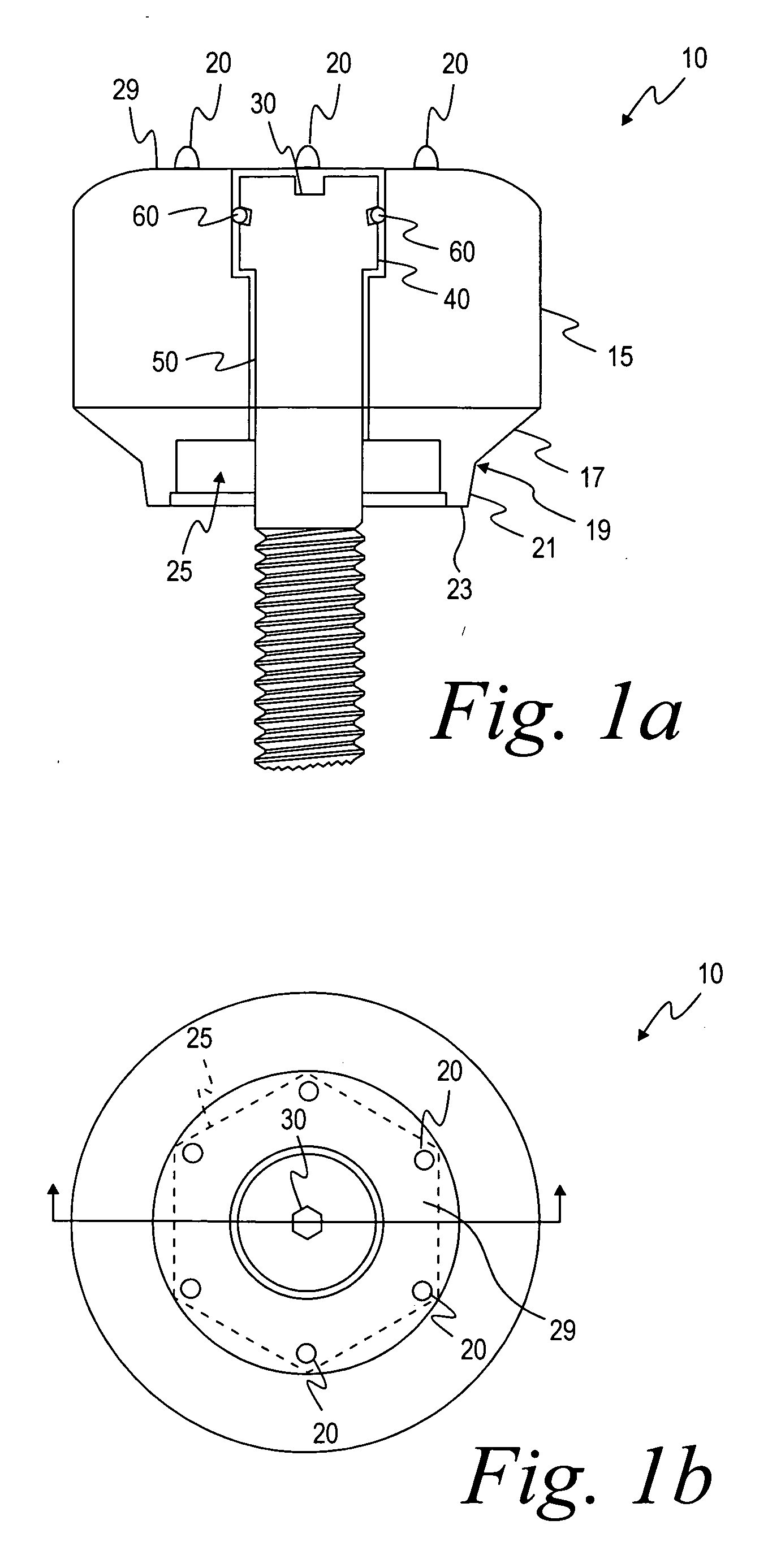
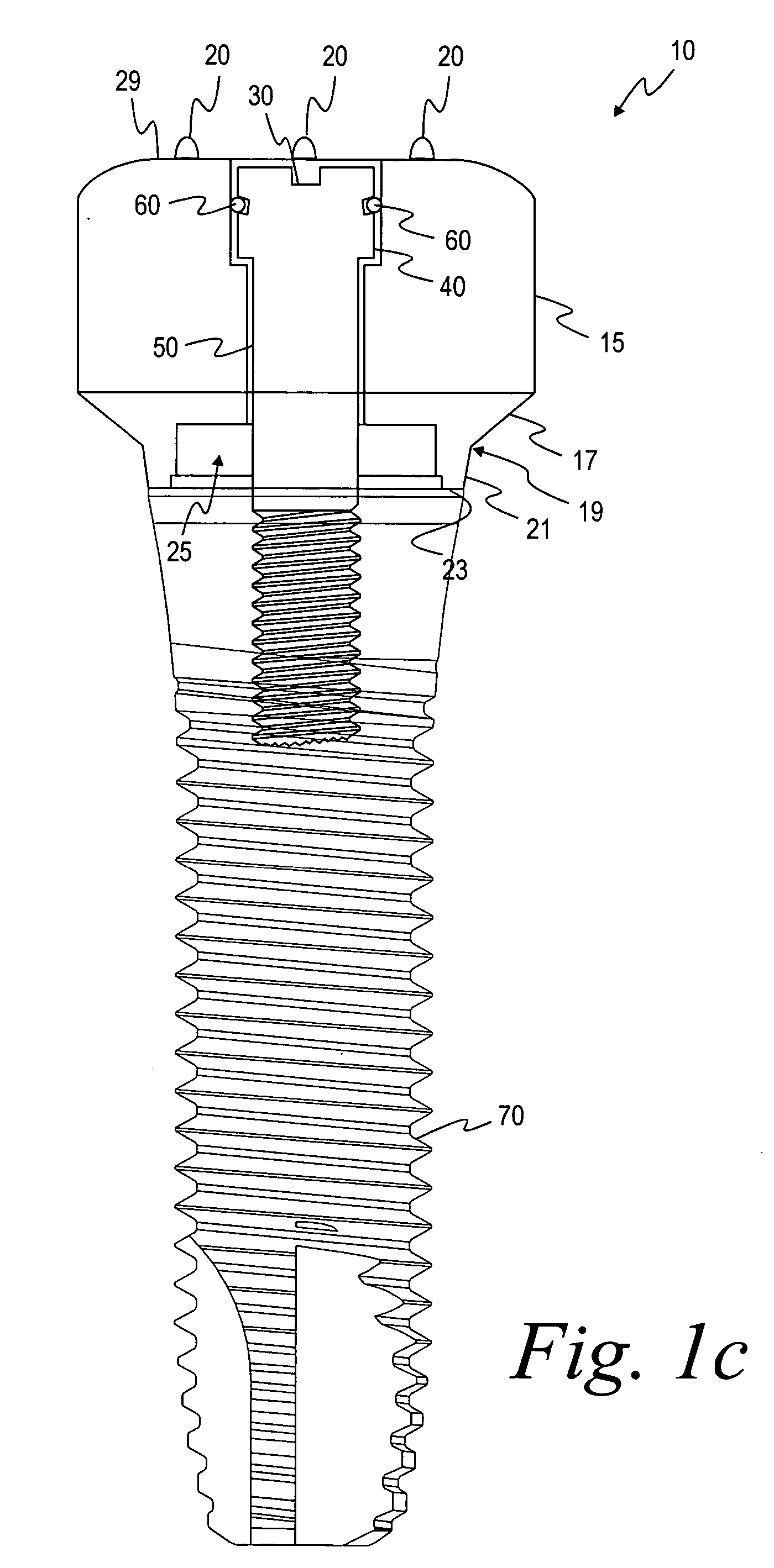
[0052] As shown in FIG. 1a and 1b, the healing abutment 10 of one embodiment of the present invention has a main body 15 with a generally circular cross-sectional shape, a first tapered section 17, a boundary 19, a second tapered section 21, an end surface 23, a hex socket 25 and dimensions that are generally suitable for replicating the emergence profile of a natural tooth. The first tapered section 17 extends downwardly from the main body 15 of the abutment 10 having a diameter at a boundary 19 that is generally larger than the implant (not shown). The boundary 19 separates the first tapered section 17 from the second tapered section 21 that terminates in the end surface 23. The second tapered section 21 is at an angle with the central axis of the implant that is generally in the range from about 5 degrees to about 15 degrees, with 10 degrees being preferable. Alternatively, the second tapered section 21 may be omitted such that the first tapered section 17 tapers directly to the ...


PUM


Abstract

A method of manufacturing a rapid prototype overmold for locating a dental implant analog in a modified stone model for use in creating a tooth prosthesis is provided. An impression of a mouth having a first installation site that has a dental implant and a gingival healing abutment with at least one informational marker installed is taken. A stone model based on the impression is prepared. The model is scanned. A three-dimensional computer model of the installation site on a CAD program using data from the scan is created. The at least one informational marker is determined to gather information about the location of the dental implant. Abutment dimensional information based on the three-dimensional image and the at least one informational marker is developed. Overmold rapid prototype dimensional information based on the three-dimensional image is developed. The overmold rapid prototype adapted to fit over the modified stone model is fabricated.

Description

RELATED APPLICATIONS [0001] This application claims the benefit of U.S. Provisional Patent Application No. 60 / 729,506 filed on Oct. 24, 2005 and entitled “Methods for Manufacturing Dental Implant Components” and this provisional application is herby incorporated by reference in its entirety.FIELD OF INVENTION [0002] The present invention relates generally to dental implant systems. More particularly, the present invention relates to restoration components for dental implant systems and a computer model for developing an implant analog placement tool to eliminate the need for a surgical index. BACKGROUND OF THE INVENTION [0003] The dental restoration of a partially or wholly edentulous patient with artificial dentition is typically done in two stages. In the first stage, an incision is made through the gingiva to expose the underlying bone. An artificial tooth root, usually a dental implant, is placed in the jawbone for integration. The dental implant generally includes a threaded bo...

Claims


Application Information

Patent Timeline
IPC IPC(8): A61C11/00
CPCA61C13/0004A61C9/0053A61C13/0019B33Y50/00B33Y80/00A61C1/00
Inventor POWELL, THEODOREBERCKMANS, BRUCESUTTIN, ZACHARYROGERS, DANROBB, T.
Owner BIOMET 3I LLC
Why Eureka
Try Eureka