Dynamic spinal stabilizer

a spinal stabilizer and dynamic technology, applied in the field of spinal stabilizers, can solve the problems of accelerating degeneration at those levels, reducing range of motion, and increasing load transfer to adjacent levels of the spine, and achieves substantial dimensional/diametrical stability and the effect of enhancing the likelihood of rapid adoption

Inactive Publication Date: 2007-04-26
APPLIED SPINE TECH
View PDF99 Cites 127 Cited by
  • Summary
  • Abstract
  • Description
  • Claims
  • Application Information

AI Technical Summary

Benefits of technology

[0016] The elongated members / spinal support rods in accordance with the present disclosure are compatible (e.g., by virtue of standard diameter sizing, substantial dimensional / diametrical stability, and / or rigidity in axial tension and axial compression, etc.) with most rod attachment hardware presently being implanted in conjunction with lumbar fusion surgery, enhancing the likelihood of quick adoption by the medical community and / or governmental regulatory approval;

Problems solved by technology

While fusion is a well-established procedure that is effective about seventy percent of the time, there are consequences even to successful fusion procedures, including a reduced range of motion and an increased load transfer to adjacent levels of the spine, which may accelerate degeneration at those levels.
Further, a significant number of back-pain patients, estimated to exceed seven million in the U.S., simply endure chronic low-back pain, rather than risk procedures that may not be appropriate or effective in alleviating their symptoms.
In general, while great strides are currently being made in the development of motion preservation devices, the use of such devices is not yet widespread.

Method used


Image

  • Dynamic spinal stabilizer
  • Dynamic spinal stabilizer
  • Dynamic spinal stabilizer

Examples


Embodiment Construction

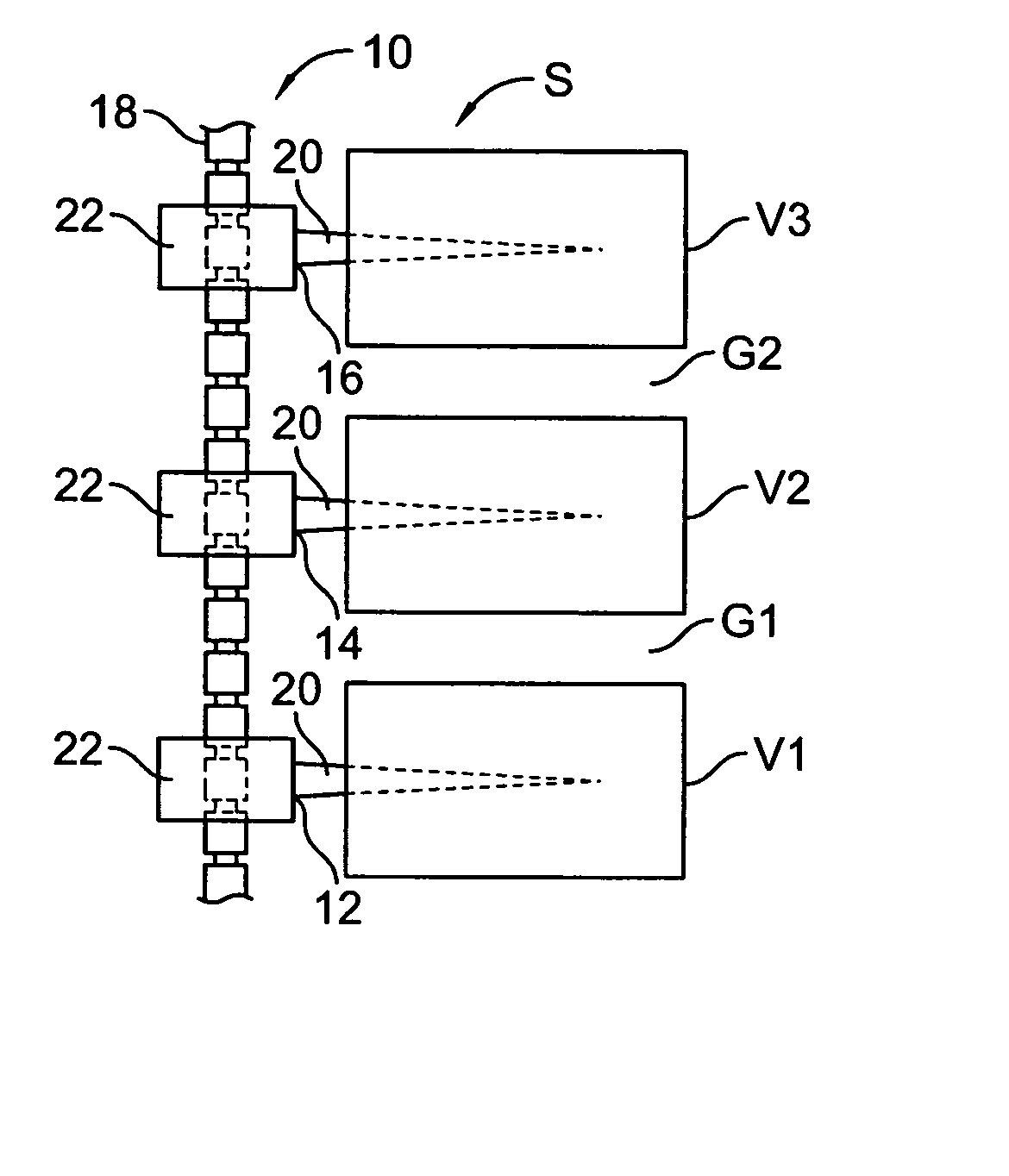
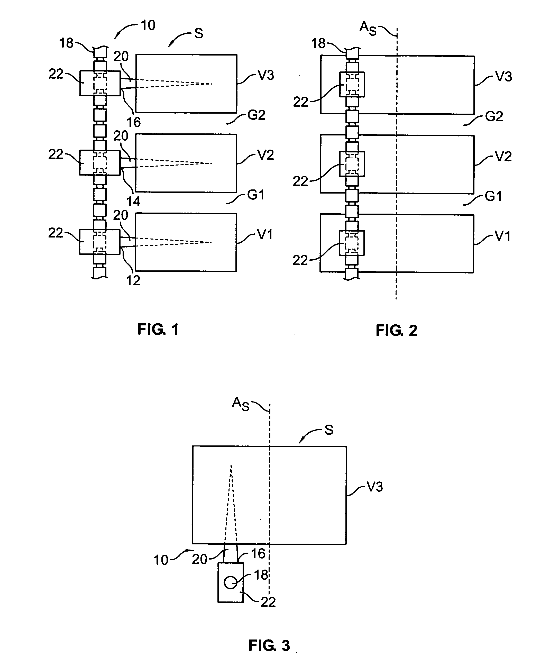
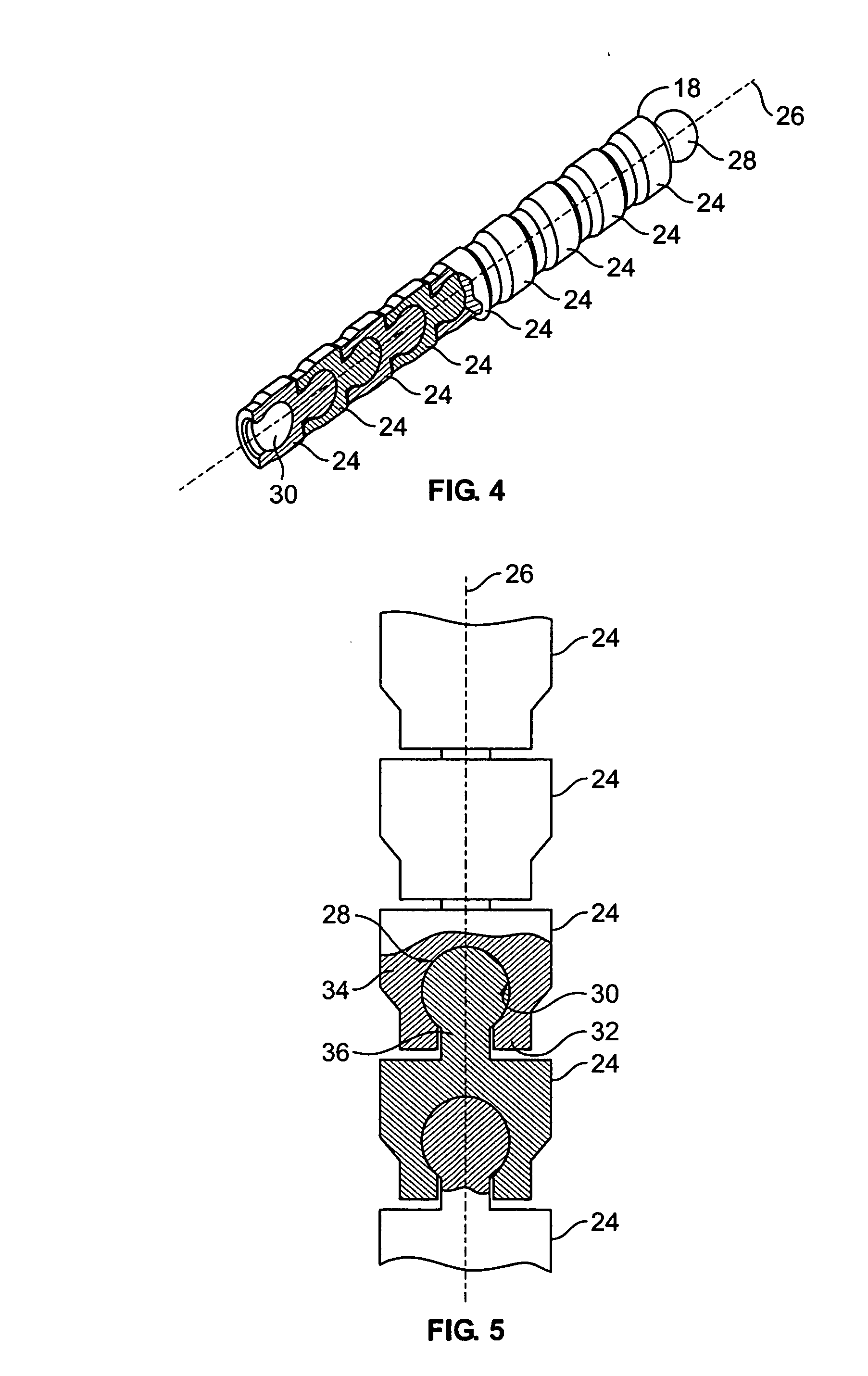
[0036] The present disclosure provides advantageous devices, systems and methods for providing dynamic spinal stabilization. More particularly, the present disclosure provides elongated members and / or spinal support rods that are suitable for surgical implantation across one or more spinal levels for purposes of support and stabilization in flexion, extension, and / or axial rotation, and that include an axially articulable geometry and / or angulation means along transverse directions so as to permit the patient at least some range of motion in spinal flexion, extension, and / or axial rotation while still being capable of providing efficacious support and / or stabilization to the spine.

[0037] The exemplary embodiments disclosed herein are illustrative of the advantageous spinal stabilization devices / systems and surgical implants of the present disclosure, and of methods / techniques for implementation thereof. It should be understood, however, that the disclosed embodiments are merely exe...


PUM


Abstract

An elongated member forming a spinal support rod is implantable adjacent the spine of a patient and includes an axial span or spans for spanning respective spinal levels to promote efficacious spinal support/stabilization. The axial span has an axially articulable geometry, and manifests an angulation mechanism along one or more transverse directions of at least seven degrees across a given spinal level. The angulation mechanism may be associated with joints between structural elements assembled in serial along the axial span, or via a common connection between such structural elements and a restraining element. Rotation between such structural elements can be global. The axial span may have a rod-like profile of a diameter similar to conventional spinal support rods used for lumbar spinal fusion, and provides for use across multiple spinal levels and with multiple adjustable attachment points for associated spine attachment devices to accommodate different patient anatomies.

Description

BACKGROUND [0001] 1. Technical Field [0002] The present disclosure relates to devices, systems and methods for spinal stabilization. More particularly, the present disclosure relates to devices, systems and methods for providing dynamic stabilization to the spine via the use of elongated members spanning one or more spinal levels. [0003] 2. Background Art [0004] Each year, over 200,000 patients undergo lumbar fusion surgery in the United States. While fusion is a well-established procedure that is effective about seventy percent of the time, there are consequences even to successful fusion procedures, including a reduced range of motion and an increased load transfer to adjacent levels of the spine, which may accelerate degeneration at those levels. Further, a significant number of back-pain patients, estimated to exceed seven million in the U.S., simply endure chronic low-back pain, rather than risk procedures that may not be appropriate or effective in alleviating their symptoms. ...

Claims


Application Information

Patent Timeline
Patent Type & Authority Applications(United States)
IPC IPC(8): A61F2/30
CPCA61B17/7001A61B17/7004A61B17/7023A61B17/7029A61B17/7031
Inventor CALLAHAN, RONALD IICORRAO, ERNESTMAGUIRE, STEPHENSANTANGELO, STEPHEN
Owner APPLIED SPINE TECH
Why Eureka
Try Eureka