Dynamic spinal stabilizer

Inactive Publication Date: 2007-04-26
APPLIED SPINE TECH
View PDF99 Cites 100 Cited by
  • Summary
  • Abstract
  • Description
  • Claims
  • Application Information

AI Technical Summary

Benefits of technology

[0015] The elongated members/spinal support rods in accordance with the present disclosure are compatible (e.g., by virtue of standard diameter sizing, substantial dimensional/diametrical stability, and/or rigidity in axial tension and axial compres

Problems solved by technology

While fusion is a well-established procedure that is effective about seventy percent of the time, there are consequences even to successful fusion procedures, including a reduced range of motion and an increased load transfer to adjacent levels of the spine, which may accelerate degeneration at those levels.
Further, a significant number of back-pa

Method used


Image

  • Dynamic spinal stabilizer
  • Dynamic spinal stabilizer
  • Dynamic spinal stabilizer

Examples


Embodiment Construction

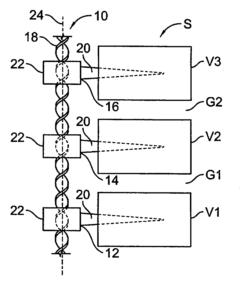
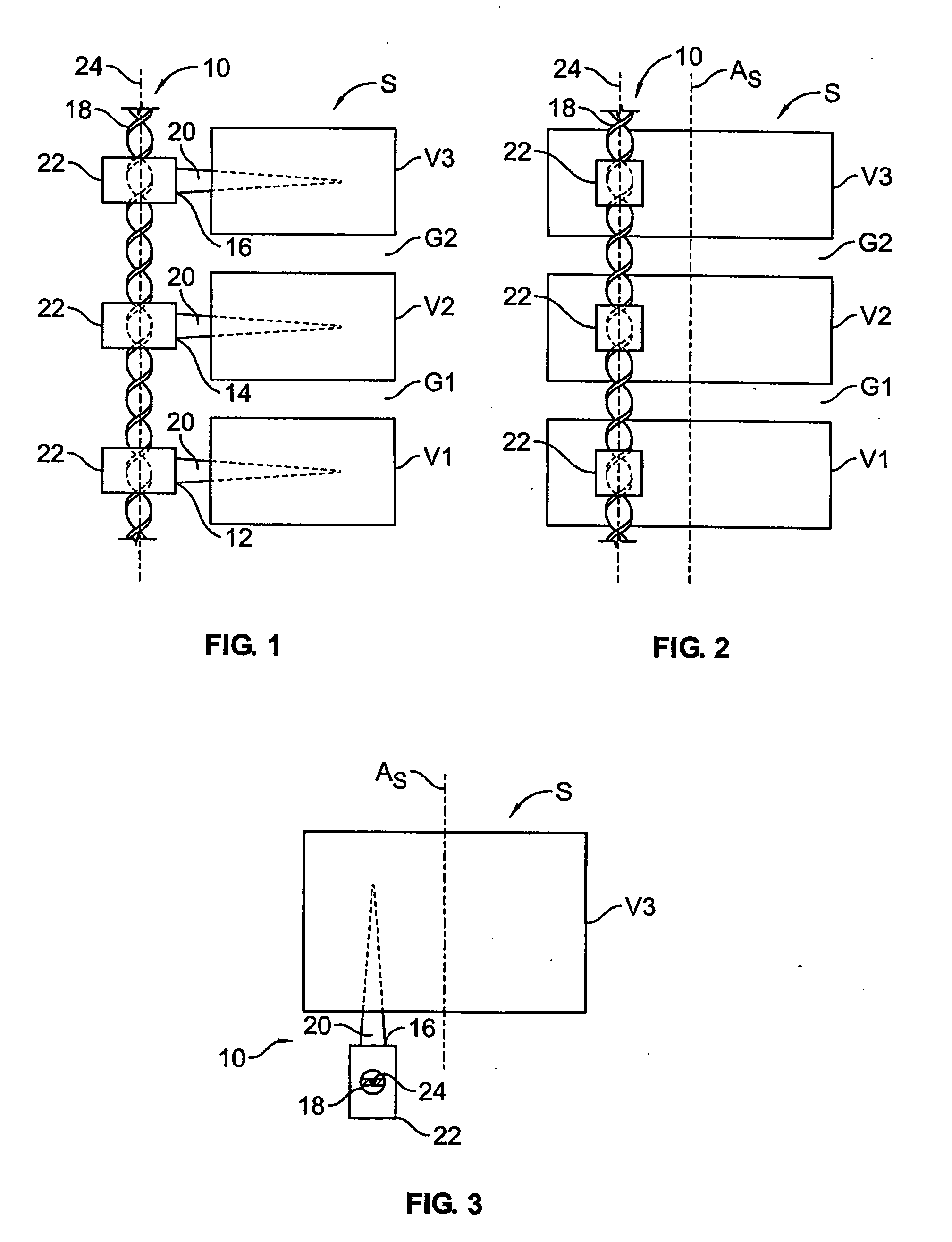
[0028] The present disclosure provides advantageous devices, systems and methods for providing dynamic spinal stabilization. More particularly, the present disclosure provide elongated members in the form of rods that are suitable for surgical implantation across multiple spinal levels for purposes of support and stabilization in flexion, extension, and / or axial rotation, and that are also laterally flexible so as to provide a range of motion in spinal flexion, extension, and / or axial rotation.

[0029] The exemplary embodiments disclosed herein are illustrative of the advantageous spinal stabilization devices / systems and surgical implants of the present disclosure, and of methods / techniques for implementation thereof. It should be understood, however, that the disclosed embodiments are merely exemplary of the present invention, which may be embodied in various forms. Therefore, the details disclosed herein with reference to exemplary dynamic stabilization systems and associated metho...


PUM


Abstract

An elongated member forming a spinal support rod is implantable adjacent the spine of a patient and includes an axial span or spans for spanning respective spinal levels to promote efficacious spinal support/stabilization. The axial span manifests a double helical geometry. The axial span has a rod-like profile of a diameter similar to conventional spinal support rods used for lumbar spinal fusion, and provides for use across multiple spinal levels and with multiple adjustable attachment points for associated spine attachment devices, such as pedicle screws, to accommodate different patient anatomies.

Description

BACKGROUND [0001] 1. Technical Field [0002] The present disclosure relates to devices, systems and methods for spinal stabilization. More particularly, the present disclosure relates to devices, systems and methods for providing dynamic stabilization to the spine via the use of elongated members spanning one or more spinal levels. [0003] 2. Background Art [0004] Each year, over 200,000 patients undergo lumbar fusion surgery in the United States. While fusion is a well-established procedure that is effective about seventy percent of the time, there are consequences even to successful fusion procedures, including a reduced range of motion and an increased load transfer to adjacent levels of the spine, which may accelerate degeneration at those levels. Further, a significant number of back-pain patients, estimated to exceed seven million in the U.S., simply endure chronic low-back pain, rather than risk procedures that may not be appropriate or effective in alleviating their symptoms. ...

Claims


Application Information

Patent Timeline
IPC IPC(8): A61F2/30
CPCA61B17/7001A61B17/701A61B17/7026A61B17/7028A61B17/7029
Inventor CALLAHAN, RONALD IICORRAO, ERNESTMAGUIRE, STEPHENSANTANGELO, STEPHEN
Owner APPLIED SPINE TECH
Why Eureka
Try Eureka