
Bone screw apparatus, system and method

a bone screw and screw body technology, applied in the field of orthopedic implants, can solve the problems of limiting the design, reducing the service life of the bone screw,

Active Publication Date: 2007-04-26
ZIMMER BIOMET SPINE INC
View PDF25 Cites 144 Cited by
  • Summary
  • Abstract
  • Description
  • Claims
  • Application Information

AI Technical Summary

Problems solved by technology

However, such designs are not without limitation.
Specifically, such conventional designs limit the positioning of the rod such that it is aligned with and / or above the screw.
As a result, a surgeon is forced to try and position the screw taking into account the position of the rod and being generally unable to move the screw into the most optimal or strategic position.
These limitations may cause the surgeon to reposition the bone screw in order to correctly align the system and as a result cause additional and unnecessary weakening of the bone due to, for example, additional screw holes created by the repositioning and / or stress on the bone screw interface by forcible repositioning.
Further, while some bone screws allow for limited radial movement of the coupling element, medial-lateral variability of the placement of these rods relative to the screw is curtailed.

Method used


Image

  • Bone screw apparatus, system and method
  • Bone screw apparatus, system and method
  • Bone screw apparatus, system and method

Examples


Embodiment Construction

[0020] As used herein, the following definitional terms apply. The term “anterior” and “posterior” mean nearer to the front or the back of the body respectively. “Proximal” and “distal” mean nearer and farther from the center of the body respectively. “Medial” and “lateral” mean nearer or farther from the median plane respectively. The median plane is an imaginary, vertical plane that divides the body into a right and left half. A coronal plane is an imaginary, vertical plane that divides the body into a front half and a back half. “Superior” and “inferior” mean above or below respectively. “Sagittal” means a side profile.

[0021] The present invention provides for a bone screw apparatus, system, and method for attaching a connector to a vertebra.

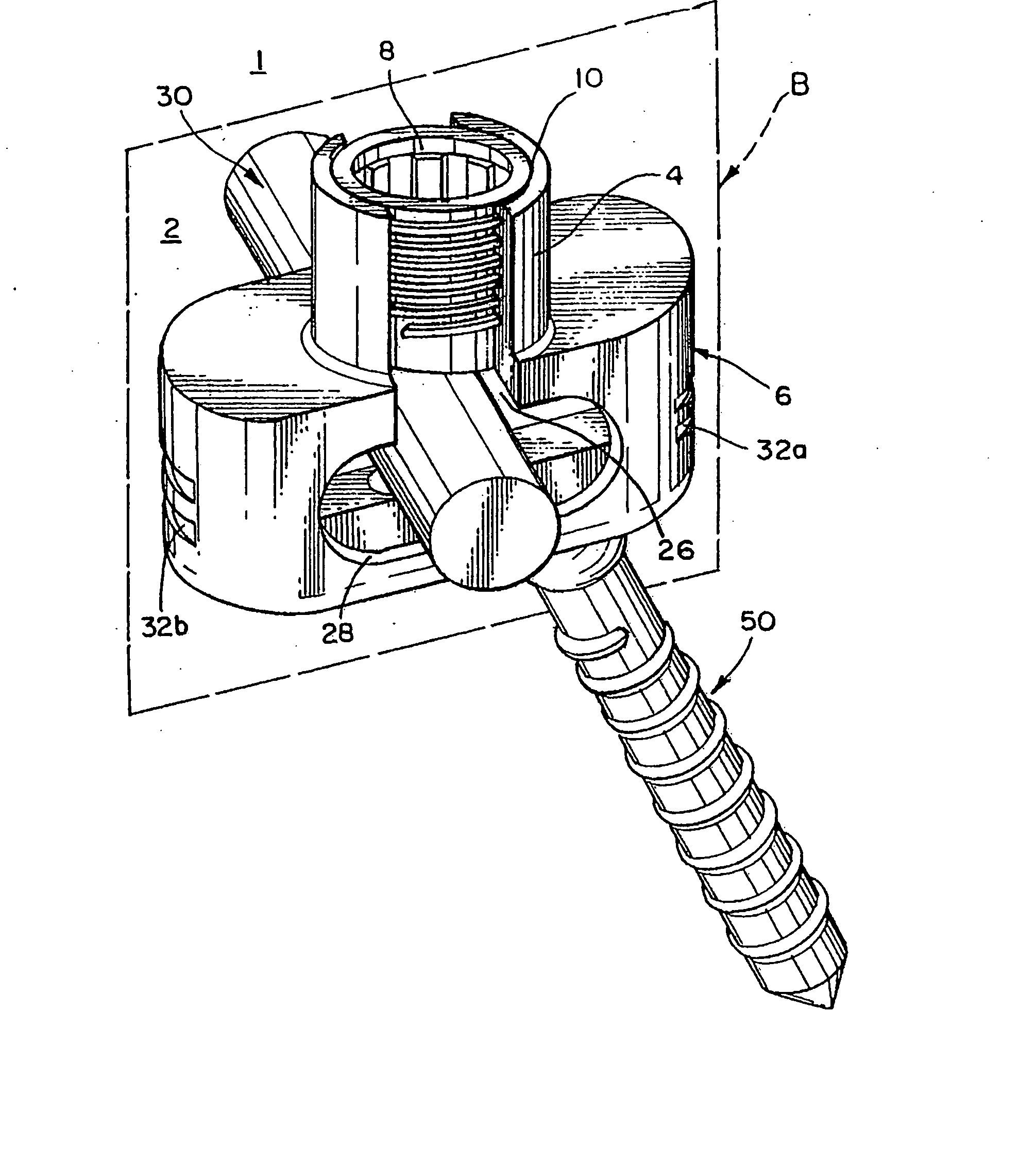
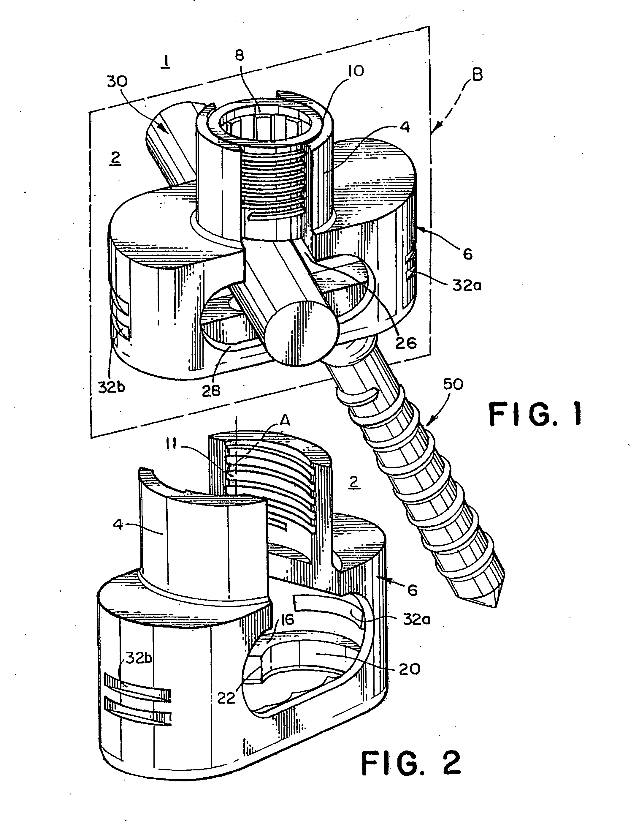
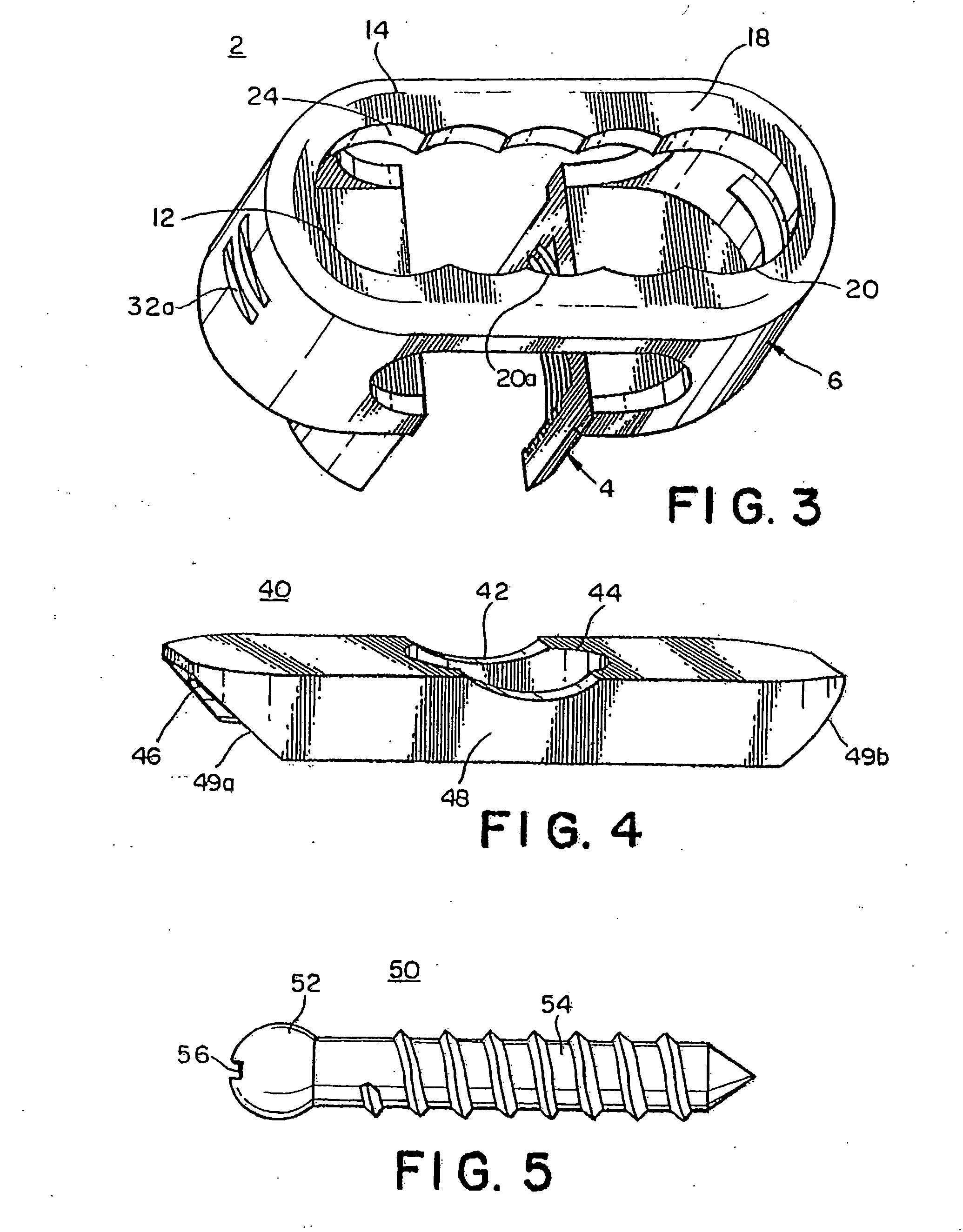
[0022] In an embodiment, as illustrated in FIGS. 1-5, the present invention provides for a bone screw apparatus 1 that includes a coupling element 2, a fixation element 8, a connector 30, a locking wedge 40, and a bone screw 50.

[0023] As i...


PUM


Abstract

A bone screw apparatus, system, and method for assisting in the placement and alignment of a bone screw and for aligning bone are described. The present invention allows a surgeon to position a bone screw in a desired position and adjust a coupling element in a variety of positions and angles with respect to the bone screw.

Description

BACKGROUND OF THE INVENTION [0001] 1. Field of the Invention [0002] The present invention relates to an orthopedic implant. In particular, the present invention relates to a bone screw apparatus, system, and method. [0003] 2. Description of Related Art [0004] Conventional bone screws and precursory polyaxial screws have found wide usage in orthopedic spinal surgery. Such devices are routinely used to address spinal instability and displacement, genetic or developmental irregularities, trauma, chronic stress, tumors, and disease. However, such designs are not without limitation. For example, conventional bone screws used with fixation rods , provide for minimal, if any variability in the placement of these rods relative to the position of the bone screw. Specifically, such conventional designs limit the positioning of the rod such that it is aligned with and / or above the screw. The rod itself makes direct contact with the screw head and is used to secure the screw into a coupling ele...

Claims


Application Information

Patent Timeline
IPC IPC(8): A61F2/30
CPCA61B17/7034A61B17/7037A61B17/7038A61B17/70
Inventor ALBERT, TODD J.
Owner ZIMMER BIOMET SPINE INC
Learn More