Method and apparatus for mapping objects to multiple tables of a database

a database and object technology, applied in relational databases, data processing applications, instruments, etc., can solve problems such as inability to perform dbms operations such as update, limit accessibility or knowledge of such a column, and cannot be used to update base tables

Inactive Publication Date: 2007-04-26
NEXT
View PDF5 Cites 33 Cited by
  • Summary
  • Abstract
  • Description
  • Claims
  • Application Information

AI Technical Summary

Problems solved by technology

Therefore, some DBMS operations, such as update, cannot be performed on a view.
In the above example, the exclusion of the “budget” column from the view limits accessibility or knowledge that such a column exists.
One disadvantage of views is that they are read-only.
Therefore, a view cannot be used to update the base tables that actually contain the data used to create a view.
Another disadvantage of views is that a DBMS restricts the operations that are required to create a view.
There are several disadvantages with the current object-oriented systems' techniques for mapping DBMS data to objects.
Therefore, the DBMS-to-object mapping is not transparent to the user (e.g., the application developer).
Further, the program code needed to implement this mapping increases the size and complexity of the application.
The increased coding results in an increase in the amount of the effort needed to debug and maintain the program code.
Further, the DBMS-to-object mapping is not dynamic.
Another disadvantage relates to the restrictions that are placed on the DBMS schema and / or DBMS-to-object mapping that can be supported by the current object-oriented systems.
Further, because there must be a one-to-one correspondence between a table and object, it is not possible to map multiple tables to a single object.
Thus, in the example described above, it is not possible to map the columns included in the virtual table (i.e., columns from the employee table plus the employee's department description from the department table) to the properties of a single object.

Method used


Image

  • Method and apparatus for mapping objects to multiple tables of a database
  • Method and apparatus for mapping objects to multiple tables of a database
  • Method and apparatus for mapping objects to multiple tables of a database

Examples


Embodiment Construction

[0044] A method and apparatus for mapping objects to multiple tables of a database is described. In the following description, numerous specific details are set forth in order to provide a more thorough C ascription of the present invention. It will be apparent, however, to one skilled in the art, that the present invention may be practiced without these specific details. In other instances, well-known features have not been described in detail so as not to obscure the invention.

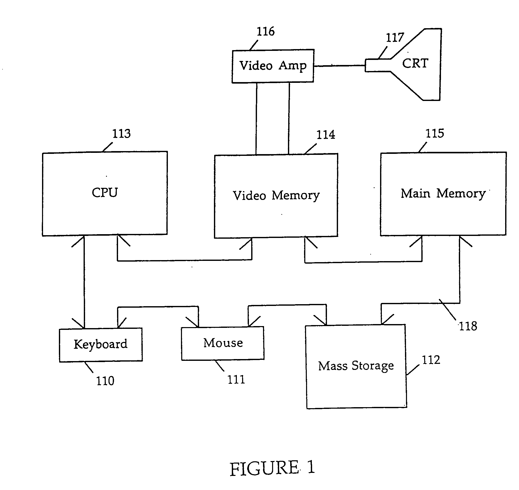
[0045] The present invention can be implemented on a general purpose computer such as illustrated in FIG. 1. A keyboard 110 and mouse 111 are coupled to a bi-directional system bus 118. The keyboard and mouse are for introducing user input to the computer system and communicating that user input to CPU 113. The computer system of FIG. 1 also includes a video memory 114, main memory 115 and mass storage 112, all coupled to bi-directional system bus 118 along with keyboard 110, mouse 111 and CPU 113. The mass...


PUM


Abstract

The present invention creates a model that maps object classes in an object-oriented environment to a data source. The model maps the relationship between properties of each object class and data of the data source. The present invention can be used with a data source such as a relational database, user interface, file system, or object-oriented database. An application's object classes and data source schema are designed independent of the other since the model can be used to map one to the other. The model is comprised of entities and attributes. An entity maps to an object class and to at least one table of the DBMS. An entity contains attributes either simple or derived. A simple attribute maps to a DBMS column. A derived attribute is a combination of other attributes and does not directly map to a DBMS column. A relationship creates a link between entities of the model. A relationship can be used to flatten an attribute or flatten a relationship. A flattened attribute is an attribute of one entity that is added to another entity. A flattened relationship is created by the elimination of intermediate relationships between two entities. Relationships can be either unidirectional or bi-directional. A unidirectional relationship has a single traversal path that has a source entity and a destination. A bi-directional relationship has two traversal paths. A reflexive relationship can be created using a single entity. The model is used to synchronize object properties and the data of the data source.

Description

BACKGROUND OF THE INVENTION [0001] 1. Field of the Invention [0002] This invention relates to mapping of data to objects in an object-oriented environment. [0003] 2. Background Art [0004] In a database management system (DBMS), data is stored in rows of tables. Each row contains one or more fields or columns. Each column contains an item of data. For example, an employee table contains rows of employee records. Each row, or record, contains information regarding an employee. An employee record can contain, for example, a last name column that contains a last name of the employee. [0005] Data stored in a column of a table can form the basis of a relationship between another table in the database having a related column. A relationship can also be formed using more than one column per table. Using a relationship between columns of two tables, it is possible to join these two tables to provide a single table containing instances of rows from one table combined with related rows from th...

Claims


Application Information

Patent Timeline
Patent Type & Authority Applications(United States)
IPC IPC(8): G06F7/00G06F17/30
CPCG06F17/3041G06F17/30595G06F17/30607Y10S707/99943Y10S707/99933Y10S707/99942Y10S707/99944G06F16/284G06F16/289G06F16/2438
Inventor WILLIAMSON, RICHARDUPSON, LINUSGREENFIELD, JACKWILLHITE, DANIEL
Owner NEXT
Why Eureka
Try Eureka