Coriolis flowmeter

a flowmeter and coriolis technology, applied in the field of coriolis flowmeters, can solve the problems of difficult to achieve high detection sensitivity and impossible to obtain a stable signal, and achieve the effect of stabilizing reducing the influence of the vibration of the flow tub

Inactive Publication Date: 2007-05-03
OVAL CORP
View PDF6 Cites 13 Cited by
  • Summary
  • Abstract
  • Description
  • Claims
  • Application Information

AI Technical Summary

Benefits of technology

[0015] According to claim 4 of the present invention, there is adopted a gate-shaped flow tube, along the straight line portion of which the drive device and the second drive devices are arranged, whereby it is possible to further stabilize the vibration of the flow tube.
[0016] According to claim 5 of the present invention, a coil requiring wiring is arranged on a stationary member parallel to the flow tube, and a magnet is arranged on the flow tube, so the influence on the vibration of the flow tube can be mitigated as much as possible.

Problems solved by technology

On the other hand, there arises a problem in that it is difficult to achieve high detection sensitivity.
Since there is provided only one flow tube, when vibrating the flow tube, it is impossible to secure the vibration balance as in the case of a flowmeter with two flow tubes, making it impossible to obtain a stable signal.

Method used


Image

  • Coriolis flowmeter
  • Coriolis flowmeter
  • Coriolis flowmeter

Examples


first embodiment

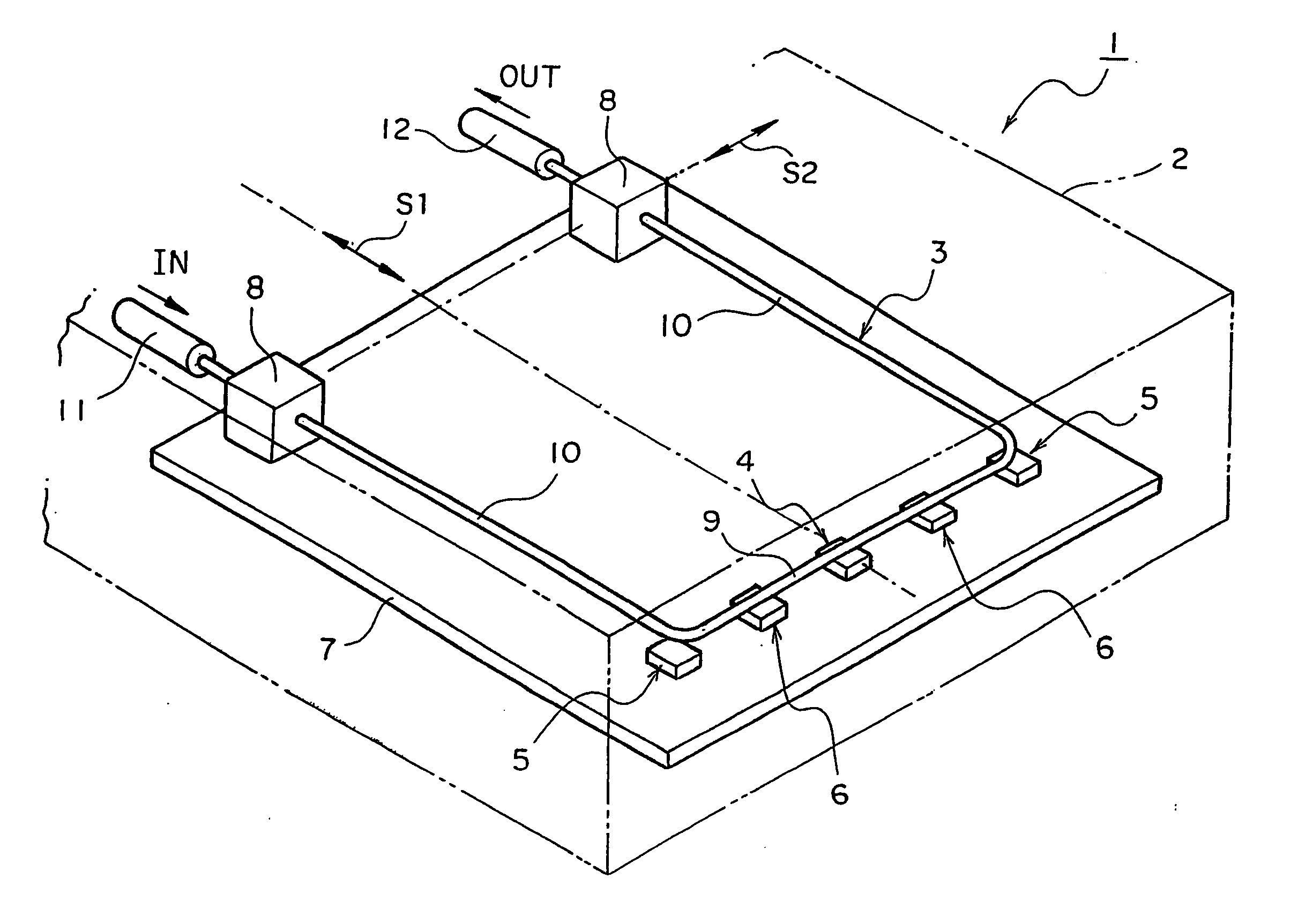
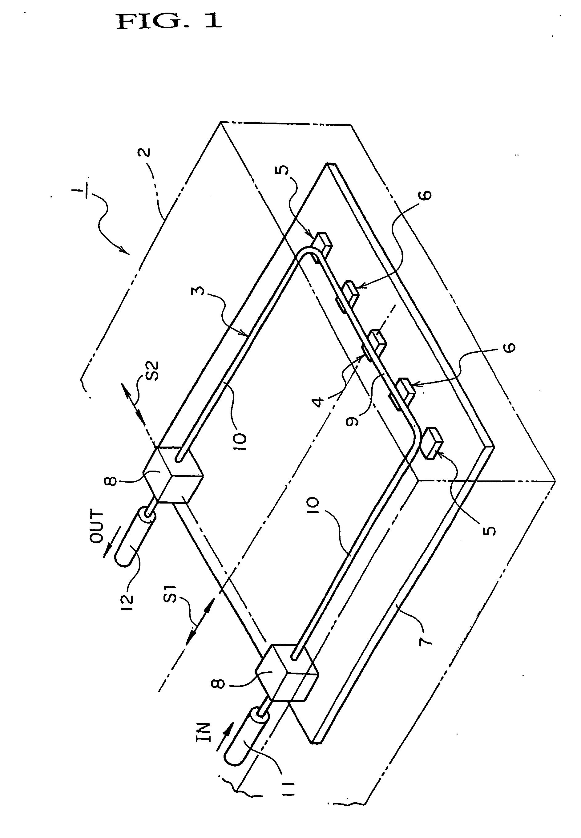
[0026] In FIG. 1, a Coriolis flowmeter according to the present invention is shown.

[0027] Of the drawings, FIG. 1 is a perspective view of a Coriolis flowmeter according to an embodiment of the present invention.

[0028] In FIG. 1, a Coriolis flowmeter 1 according to the first embodiment of the present invention includes a casing 2, a single flow tube 3 accommodated in the casing 2, a drive device 4 and a pair of second drive devices 5, 5 for driving the flow tube 3, and a pair of vibration detecting sensors 6, 6 for detecting a phase difference proportional to Coriolis forces acting on the flow tube 3. In the following, those components will be described.

[0029] The casing 2 has a structure resistant to bending and torsion. Further, the casing 2 is large enough to be capable of accommodating the flow tube 3 and a stationary member 7 arranged parallel to the plane defined by the flow tube 3 itself. Further, the casing 2 is formed so as to be capable of protecting the flow tube 3, etc...

second embodiment

[0040] Regarding the operation of the Coriolis flowmeter 1 of the present invention, it will be described below together with the operation of a Coriolis flowmeter 21 according to a

[0041] Next, a Coriolis flowmeter according to another embodiment of the present invention will be described with reference to FIGS. 2 through 4.

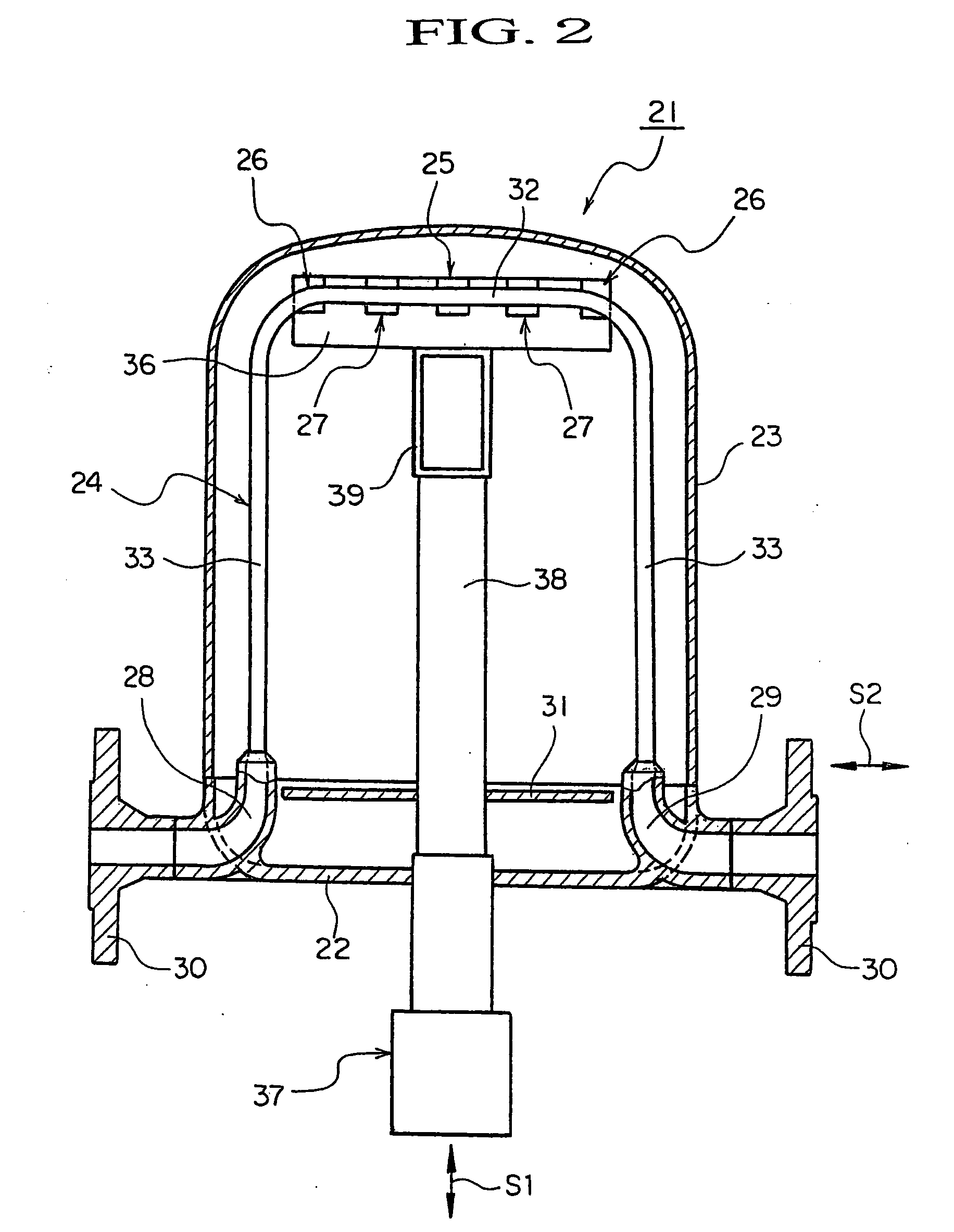
[0042]FIG. 2 shows a Coriolis flowmeter according to a second embodiment of the present invention.

[0043] Of the drawings, FIG. 2 is a front view of a Coriolis flowmeter according to an embodiment of the present invention, in which a single bent tube type flow tube is mounted in a vertical plane. FIG. 3 is a top view of the Coriolis flowmeter shown in FIG. 2; and FIG. 4 is a sectional view, as taken along a line near its center, of the Coriolis flowmeter shown in FIG. 2.

[0044] In FIGS. 2 through 4, a Coriolis flowmeter 21 according to the second embodiment of the present invention includes a main body 22 and a pressure-resistant case 23 forming a casing, a sing...

third embodiment

[0067]FIG. 7 shows a Coriolis flowmeter according to the present invention.

[0068] Of the drawings, FIG. 7 is a front view of a Coriolis flowmeter according to an embodiment of the present invention, in which a single bent tube type flow tube is mounted in a vertical plane.

[0069] In FIG. 8, a Coriolis flowmeter 21′ of the third embodiment of the present invention only differs from the Coriolis flowmeter 21 of the second embodiment described above in the arrangement of the pair of vibration detecting sensors 27. That is, in the Coriolis flowmeter of the third embodiment of the present invention, the pair of vibration detecting sensors 27, 27 are arranged between the left-hand side second drive device 26 and the inflow port on the left-hand side of the flow tube 24 and between the right-hand side second drive device 26 and the outflow port on the right-hand side of the flow tube 24.

[0070] The respective coils of the pair of vibration detecting sensors 27, 27 are mounted to a stationa...


PUM


Abstract

A flow tube (3) composed of a bent tube having a shape symmetrical with respect to a first axis is supported at its both ends by support portions (8, 8) having an outlet and inlet respectively. A drive device (4) for alternately driving the flow tube (3) rotationally about a second axis connecting the positions where the flow tube (3) is supported is disposed on the vertical axis of a Coriolis flowmeter (1).
A pair of second drive devices (5, 5) for alternately driving the flow tube (3) rotationally are disposed at positions laterally symmetrical with respect to the drive device (4). The paired second drive devices (5, 5) are driven in phase; the drive device (4) is driven with the opposite phase to those of the second drive devices (5, 5). A pair of vibration detecting sensors (6, 6) are disposed between the drive device (4) and one of the second drive device (5) and between the drive device (4) and the other (5) respectively. The sensors (6, 6) detect vibrations with phases the difference between which is in proportion to the Coriolis force acting on the flow tube (3) disposed laterally symmetrically with respect to the drive device (4).

Description

TECHNICAL FIELD [0001] The present invention relates to a Coriolis flowmeter, and more particularly to a Coriolis flowmeter including at least one flow tube constructed of a bent tube. BACKGROUND ART [0002] In a Coriolis flowmeter, a tube through which a fluid to be measured flows is supported at one end or both ends thereof, and vibration is applied to a portion of the tube around the supporting point in a direction perpendicular to the flowing direction of the tube (hereinafter, a tube to which vibration is applied is referred to as a flow tube). The Coriolis flowmeter is a mass flowmeter, which utilizes the fact that the Coriolis forces applied to the flow tube when vibration is thus applied thereto, are proportional to a mass flow rate. The Coriolis flowmeter, which is well known, is roughly classified into two types in terms of flow tube structure: a straight tube type and a bent tube type. [0003] In a Coriolis flowmeter of the straight tube type, when vibration is applied to a...

Claims


Application Information

Patent Timeline
Patent Type & Authority Applications(United States)
IPC IPC(8): G01F1/84
CPCG01F1/8409G01F1/8413G01F1/8472G01F1/84
Inventor KITAMI, HIROKAZU
Owner OVAL CORP
Why Eureka
Try Eureka