Shut-off valve system

a technology of shut-off valve and shut-off valve, which is applied in the direction of diaphragm valve, engine diaphragm, operating means/release devices of valves, etc., can solve the problems of fire damage and oftentimes exceed the damag

Inactive Publication Date: 2007-05-03
PARKER HANNIFIN CORP
View PDF12 Cites 58 Cited by
  • Summary
  • Abstract
  • Description
  • Claims
  • Application Information

AI Technical Summary

Benefits of technology

[0005] The present invention provides a shut-off valve system operative to shut-off flow through a pipe or other conduit in response to one or more fault conditions, including in particular high current that may cause damage to components downstream of the shut-off valve. The high current may result from a lightning strike inducing high current flow through the conduit and fluid flow components connected inline with the conduit.

Problems solved by technology

In the aftermath of an earthquake, the damage resulting from fires caused by gas pipe rupture or flooding from water pipe rupture can oftentimes exceed the damage resulting from shaking caused by the earthquake.

Method used


Image

  • Shut-off valve system
  • Shut-off valve system
  • Shut-off valve system

Examples


Embodiment Construction

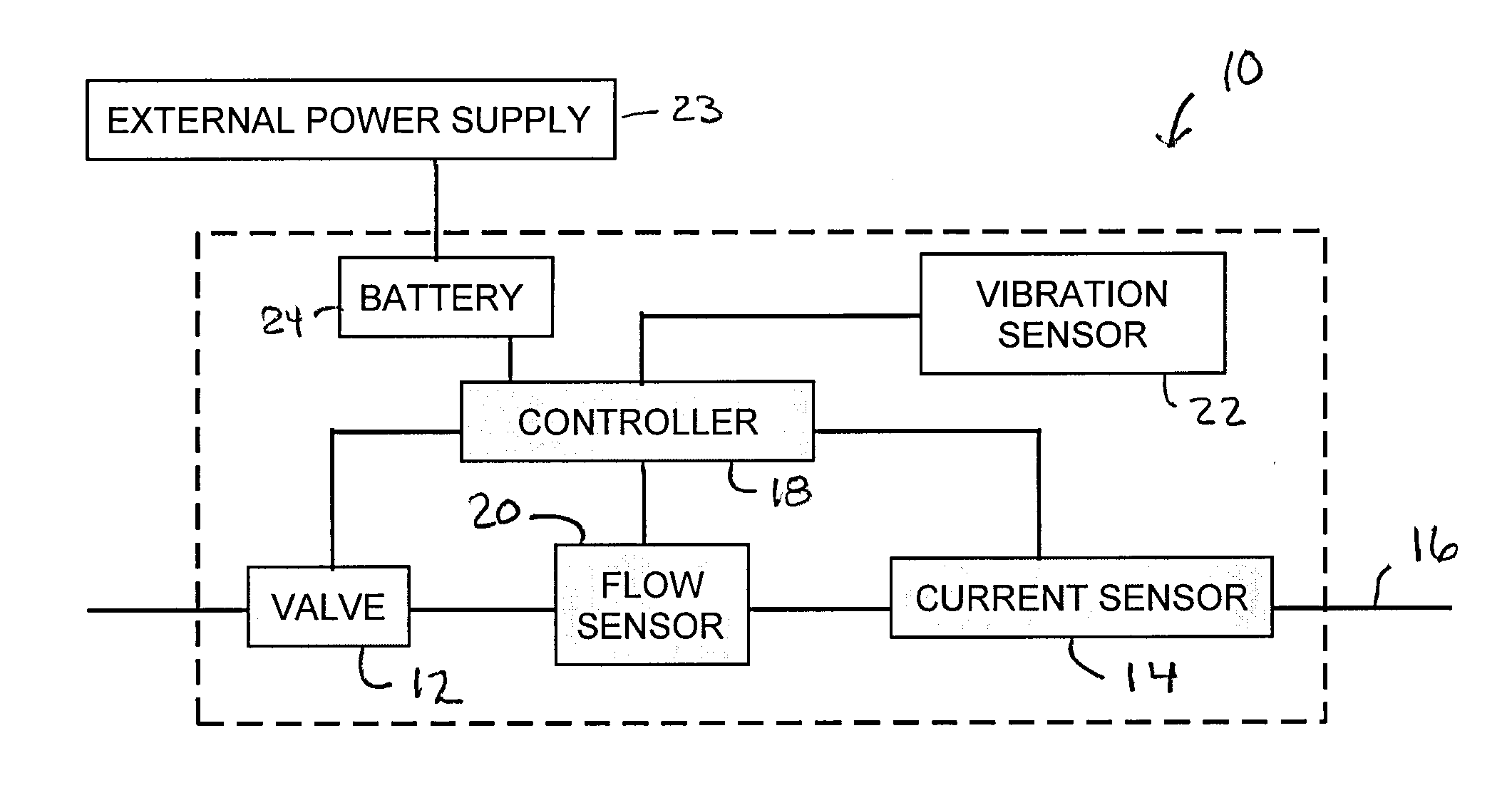
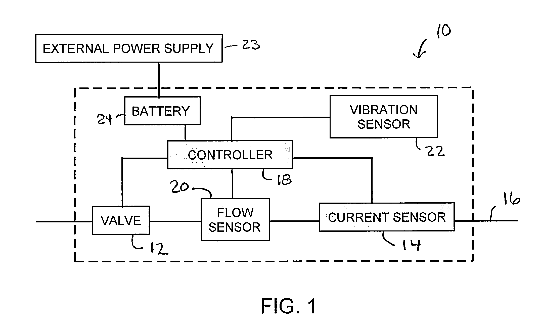
[0013] Referring now in detail to the drawings and initially to FIG. 1, an exemplary shut-off valve system according to the invention is designated generally by reference numeral 10. The valve system generally comprises a valve 12 openable and closable respectively to permit and shut-off flow through the valve; a current sensor 14 for sensing electric current passing through the valve or a conduit 16 to which the valve is connected and providing a current sensor output indicative of the sensed current; and a control device 18 for receiving the output of the current sensor and causing the shut-off valve to close if a specified criteria is satisfied, thereby to shut-off flow through the valve 12 and the downstream conduit 16 connected thereto. The system may also comprise a flow sensor 20, vibration sensor 22, and a power source for connection to an external power supply 23, or a battery 24 that may be used as a primary or more preferably as a backup power supply if external power is ...


PUM


Abstract

A shut-off valve system operative to shut-off flow through a pipe or other conduit in response to one or more fault conditions, including in particular high current that may cause damage to piping or other components downstream of the shut-off valve. The high current may result from a lightning strike inducing high current flow through the conduit and fluid flow components connected inline with the conduit.

Description

RELATED APPLICATIONS [0001] This application claims the benefit of U.S. Provisional Application No. 60 / 733,274 filed Nov. 3, 2005, which is hereby incorporated herein by reference.FIELD OF THE INVENTION [0002] The invention herein described relates generally to automatically actuated shut-off valves. More particularly, the invention relates to shut-off valve systems operative to shut-off flow through a pipe or other conduit in response to one or more fault conditions including high current that may cause damage to components downstream of the shut-off valve. BACKGROUND [0003] Natural gas or water flows from municipal gas or water mains to customer locations. At a customer location, gas or water is routed through smaller pipes into a gas or water meter. Pipes then carry the gas or water into a customer residence or business where the gas or water is ultimately used by gas-consuming devices such as furnaces or by water-consuming devices such as faucets and washing machines. [0004] Her...

Claims


Application Information

Patent Timeline
Patent Type & Authority Applications(United States)
IPC IPC(8): F16K31/12
CPCF16K7/14F16K31/06F17D5/08Y10T137/7758
Inventor BERGQUIST, THOMAS A.PIERKO, GARYHENNINGER, WILLIAM
Owner PARKER HANNIFIN CORP
Why Eureka
Try Eureka