Tube for heat exchanger and method of manufacturing the same

a technology of heat exchanger and tube, which is applied in the direction of indirect heat exchangers, laminated elements, light and heating apparatus, etc., can solve the problems of difficult to stably or uniformly form a crimped end on the tube wall, the inner fin is and the joining portions between the inner surface of the tube wall and the inner fin are likely to be displaced. , to achieve the effect of quality of joining

Inactive Publication Date: 2007-05-03
DENSO CORP
View PDF6 Cites 47 Cited by
  • Summary
  • Abstract
  • Description
  • Claims
  • Application Information

AI Technical Summary

Benefits of technology

[0014] Accordingly, a plurality of tubes can be uniformly formed. In a heat exchanger having the tubes, a clearance is uniformly defined between an end of each tube and a tube hole of a header tank. Therefore, the quality of joining between the tubes and the header tank improves.

Problems solved by technology

In the above inner fin tubes, however, when the ends of the folded tube wall are crimped even in a condition interposing the second end of the inner fin between them, the inner fin is likely to be displaced due to shrinkage of a corrugated portion of the inner fin.
If the inner fin is displaced, it is difficult to stably or uniformly form a crimped end on the tube wall.
Moreover, joining portions between an inner surface of the tube wall and the inner fin are likely to be displaced.

Method used


Image

  • Tube for heat exchanger and method of manufacturing the same
  • Tube for heat exchanger and method of manufacturing the same
  • Tube for heat exchanger and method of manufacturing the same

Examples


first embodiment

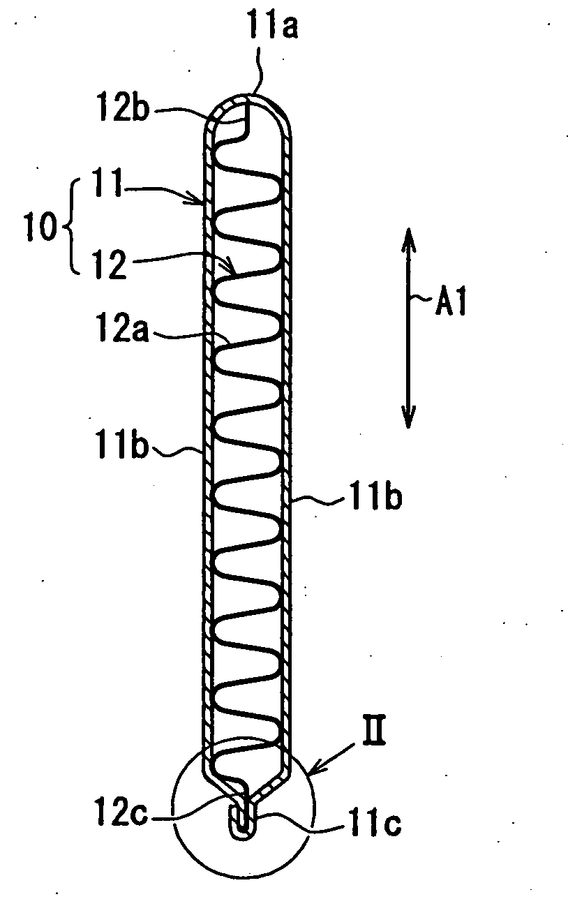
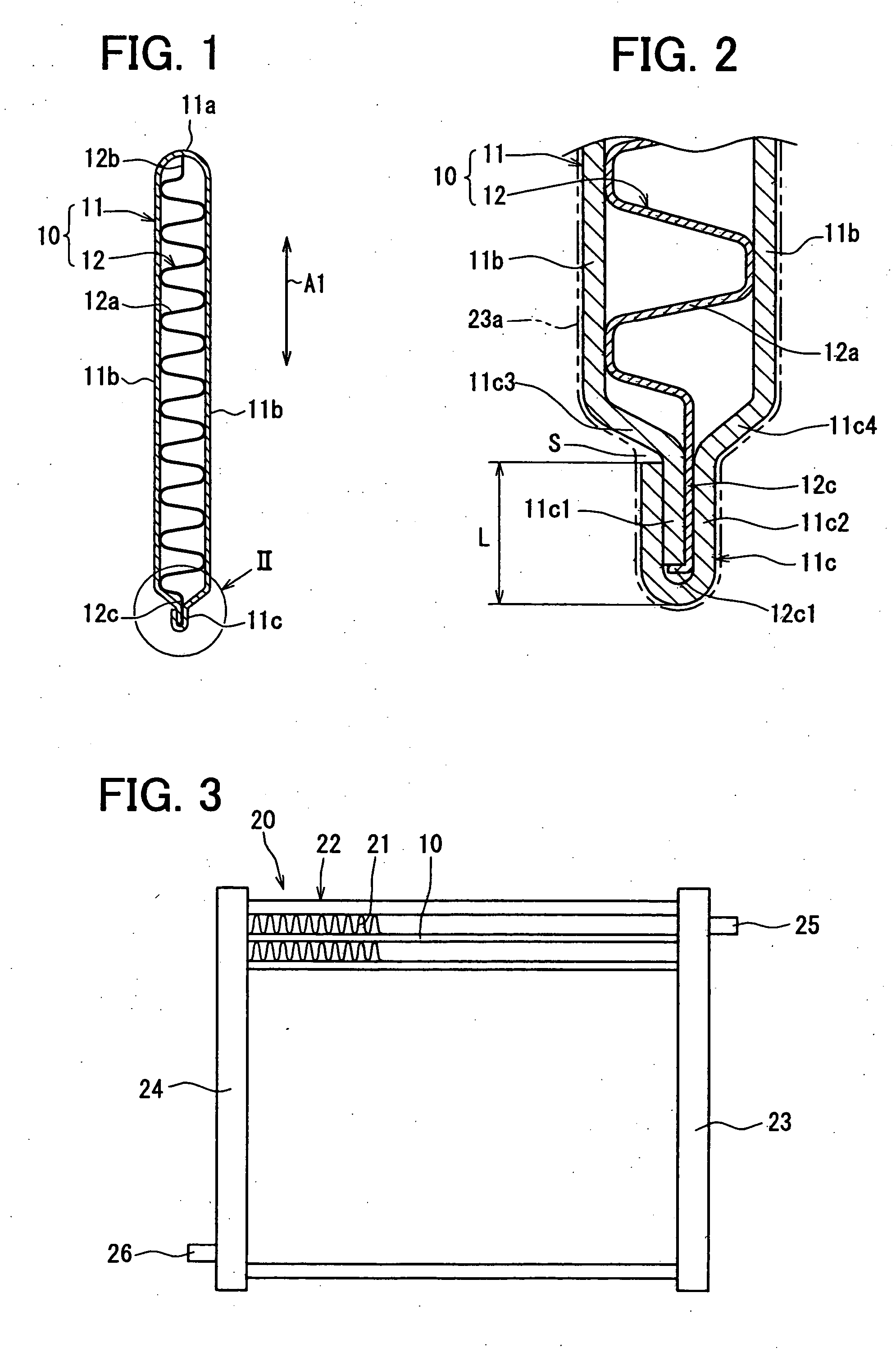
[0023] A first embodiment of the present invention will be described with reference to FIGS. 1 through 5. As shown in FIG. 1, an inner fin tube 10 of the first embodiment has a tube member 11 and an inner fin 12 inserted in the tube member 11. As shown in FIG. 3, the inner fin tube 10 is for example used as a tube of a heat exchanger 20 such as an evaporator of a refrigerating cycle.

[0024] The tube member 11 has a flat tubular shape. The tube member 11 is formed by folding a thin aluminum band plate. As shown in FIG. 1, in a cross-section defined in a direction perpendicular to a longitudinal direction of the tube member 11, the tube member 11 has a substantially elliptical shape. In FIG. 1, an arrow A1 denotes a direction parallel to a major axis of the elliptical shape.

[0025] The band plate is folded at a substantially middle portion thereof so that the tube member 11 has flat plate portions 11b and a bent portion 11a at ends of the flat plate portions 11b. The bent portion 11a ...

second embodiment

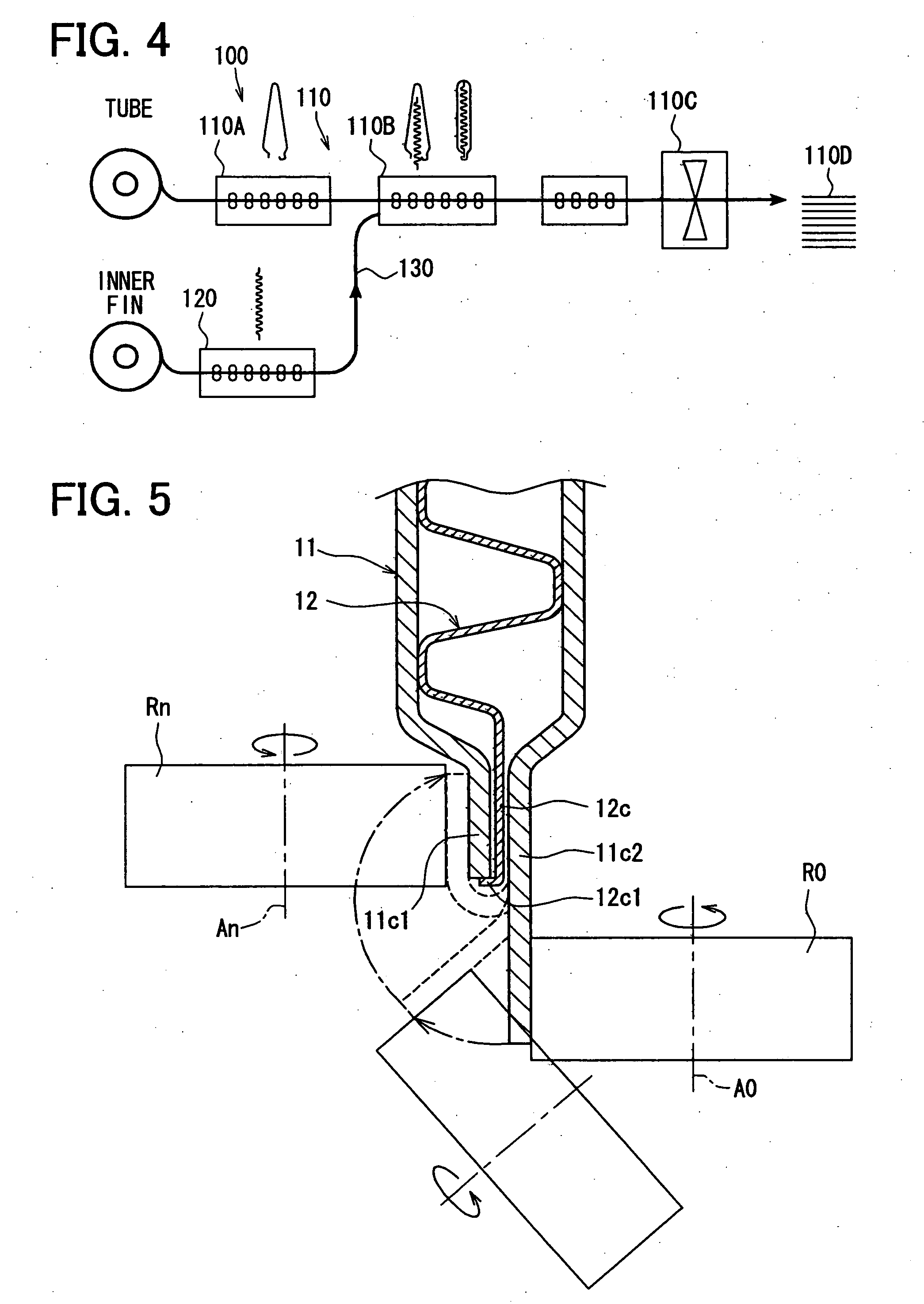
[0058] Next, a second embodiment of the present invention will be described with reference to FIGS. 6 and 7. In the second embodiment, inner fin tubes 10 have the same shape as the inner-fin tubes 10 of the first embodiment shown in FIG. 1. However, a method of manufacturing the inner fin tubes 10 is different from that of the first embodiment. FIG. 6 shows an early stage of the crimping step for crimping the first end portion 11c and the second end portion 11c2. FIG. 7 shows an intermediate stage of the crimping step.

[0059] In the second embodiment, the bent portion 12c1 of the inner fin 12 is formed at the same time as folding the second end portion 12c1 in the crimping step. In other words, the bent portion 12c1 is not formed in the inner fin forming unit 120.

[0060] In a condition that the inner fin 12 is inserted in the tube outer wall 11 in the inserting step, the second flat plate portion 12c is held between the first end portion 11c1 and the second end portion 11c2, and the...


PUM

PropertyMeasurementUnit
thicknessaaaaaaaaaa
L-shapeaaaaaaaaaa
lengthaaaaaaaaaa

Abstract

A tube for a heat exchanger has a tube member and a fin inserted in the tube member. The tube member has a first wall having a first end portion and a second wall having a second end portion. The second end portion of the second wall is folded over the first end portion of the first wall. Also, an end of the fin is held between the first end portion and the second end portion of the tube member. Further, the end of the fin has a bent portion at an end of the first end portion within the folded second end portion. The bent portion of the fin is engaged with the first end portion of the tube member for positioning the fin with respect to the tube member.

Description

CROSS REFERENCE TO RELATED APPLICATION [0001] This application is based on Japanese Patent Application No. 2005-315213 filed on Oct. 28, 2005, the disclosure of which is incorporated herein by reference. FIELD OF THE INVENTION [0002] The present invention relates to tubes for a heat exchanger such as an evaporator and a method of manufacturing the same. BACKGROUND OF THE INVENTION [0003] In a heat exchanger, tubes have inner fins therein. The tubes having the inner fins are for example manufactured in a method described in Japanese Patent Publication No. 2003-336989. Hereafter, the tubes having the inner fins are referred to as inner fin tubes. In each of the inner fin tubes, a corrugated inner fin is disposed in a tube wall having a flat tubular shape. [0004] The tube wall is for example formed by folding a band plate at a middle portion and crimping ends of the folded band plate. The tube wall has a bent portion at a first end and a crimped portion at a second end in a cross-secti...

Claims


Application Information

Patent Timeline
Patent Type & Authority Applications(United States)
IPC IPC(8): F28F1/40
CPCB21D53/02B21D53/08F16L9/17F25B39/02F28D1/0391F28F1/40F28F3/025F28F9/18F28F13/12F28F2225/04B21C37/151B21C37/225
Inventor INOUE, TOMONORIMAEDA, KENJIMITSUKAWA, KAZUHIROHATTORI, KATSUJI
Owner DENSO CORP
Why Eureka
Try Eureka