Friction spot joining device and friction spot joining method

a friction spot and joining device technology, applied in the direction of manufacturing tools, non-electric welding apparatuses, welding/soldering/cutting articles, etc., can solve the problems of shortening the life of the tool, and achieve the effect of reducing the operator's burden to adjust the joining device, and ensuring the quality of the joining devi

Active Publication Date: 2018-12-13
KAWASAKI HEAVY IND LTD
View PDF16 Cites 3 Cited by
  • Summary
  • Abstract
  • Description
  • Claims
  • Application Information

AI Technical Summary

Benefits of technology

[0010]According to the present disclosure, when carrying out the friction spot joining of the pair of plates, even if the states of the tool and/or the plates change, the joining quality is sta

Problems solved by technology

Thus, even if the states of the tool or the plates change when carrying out the friction spot joining of the plates, it can prevent that the pushing period of time of the tool into the plates and/o

Method used


Image

  • Friction spot joining device and friction spot joining method
  • Friction spot joining device and friction spot joining method
  • Friction spot joining device and friction spot joining method

Examples


embodiment

[0021]Hereinafter, one embodiment is described with reference to the drawings.

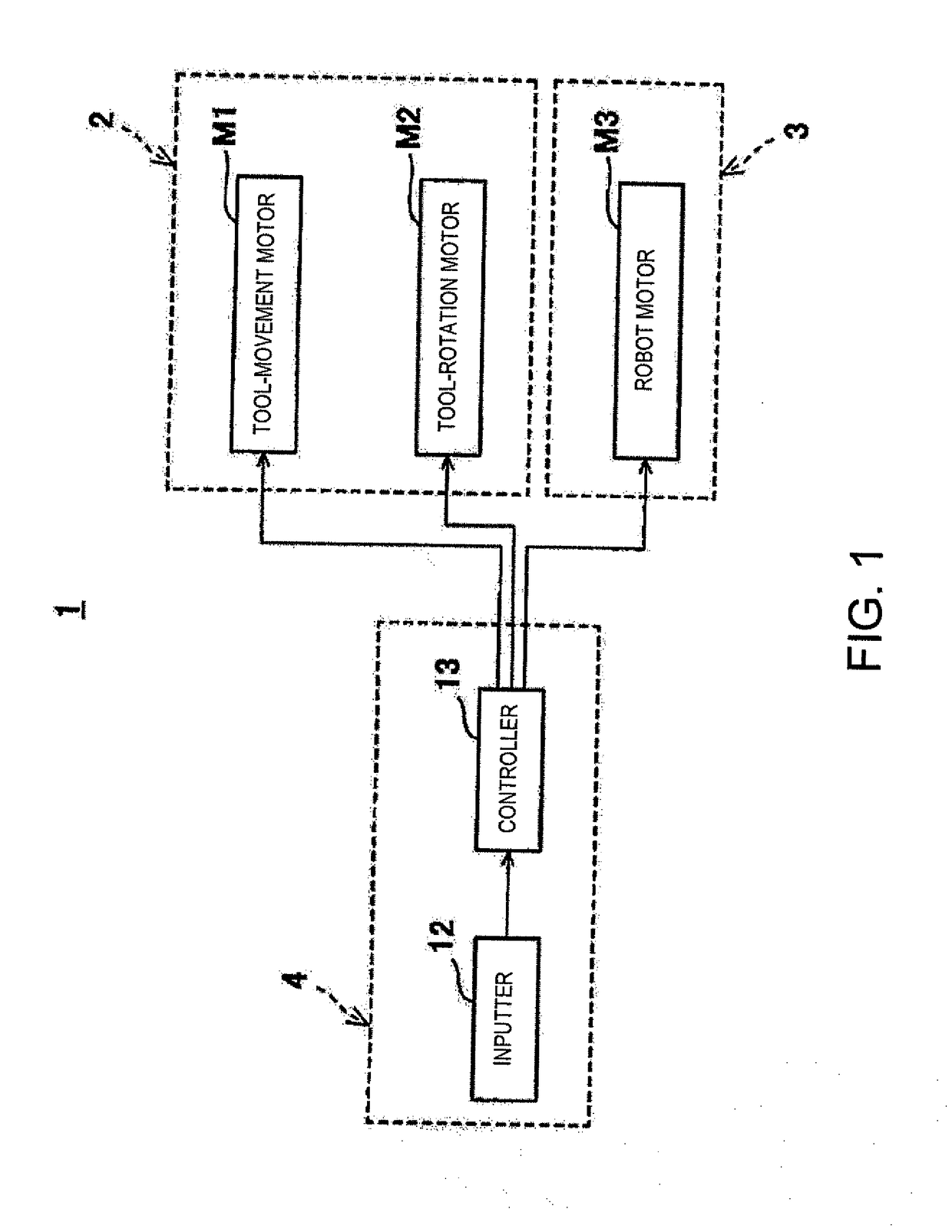
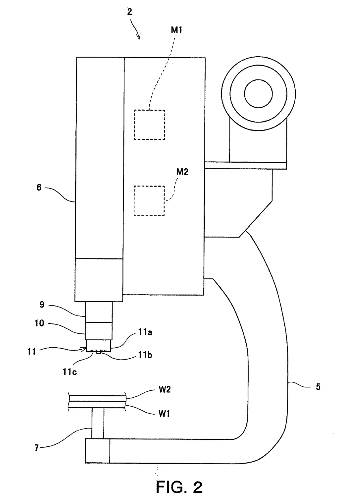
[0022]FIG. 1 is a functional block diagram of a friction spot joining device 1 (hereinafter, referred to as “the joining device 1”) according to one embodiment. FIG. 2 is a side view of a joining unit 2 provided to the joining device 1 of FIG. 1. As illustrated in FIGS. 1 and 2, the joining device 1 includes the joining unit 2, an articulated robot 3, and a control device 4. The joining unit 2 has a frame part 5, a unit main body part 6, and a backing part 7.

[0023]The frame part 5 has an appeared shape of a “C” character or an inverted “C” character in the side view as one example. The frame part 5 is connected with the unit main body part 6 and the backing part 7, and is supported by the articulated robot 3. The unit main body part 6 has a rotary shaft part 9, a tool 11, a tool-movement motor M1 (advance-retreat drive), and a tool-rotation motor M2 (rotation drive). The rotary shaft part 9 extends toward ...


PUM

PropertyMeasurementUnit
Temperatureaaaaaaaaaa
Pressureaaaaaaaaaa
Speedaaaaaaaaaa

Abstract

A friction spot joining device configured to carry out friction spot joining of a pair of plates includes an advance-retreat drive configured to advance and retreat a tool to/from the plates a rotation drive configured to rotate the tool, and a controller configured to control the advance-retreat drive and the rotation drive. The controller executes a joining control in which the tool is caused to give pressure to the plates while the tool is rotated so that the tool is pushed into the plates, and a separating control in which the tool is separated from the plates when an integrated value (P=ID×ΔT) calculated using a current value (ID) of the rotation drive during the joining control and a driving period of time (ΔT) during the joining control is determined to be reached a target value.

Description

TECHNICAL FIELD[0001]The present disclosure relates to a friction spot joining device and a friction spot joining method.BACKGROUND ART[0002]Conventionally, a friction spot joining method is known as a method of mutually joining a pair of plates. When joining the pair of plates by this method, a tool of a friction spot joining device is pushed into the pair of plates which are overlapped with each other while the tool is rotated, and is drawn out after the completion of joining, for example, as disclosed in Patent Document 1. Thus, the pair of plates are friction-spot joined.REFERENCE DOCUMENT OF CONVENTIONAL ARTPatent Document[Patent Document 1] JP3,471,338B2DESCRIPTION OF THE DISCLOSUREProblems to be Solved by the Disclosure[0003]Meanwhile, when carrying out the friction spot joining of the pair of plates, if the surface condition of the tool changes with an increase in the number of joining points or the frictional coefficient between the tool and the plates changes due to differ...

Claims


Application Information

Patent Timeline
IPC IPC(8): B23K20/12
CPCB23K20/1265B23K20/123B23K20/125B23K20/1255B23K20/126B23K20/1235B23K2101/18B23K2103/04B23K2103/10B23K20/12
Inventor FUKUDA, TAKUYAOHASHI, RYOJIMIYAKE, MASAHIROMURAMATSU, YOSHITAKAKASHIKI, HAJIME
Owner KAWASAKI HEAVY IND LTD
Why Eureka
Try Eureka