Imprinting apparatus, system and method

a technology of printing apparatus and printing machine, applied in the direction of dough shaping, manufacturing tools, instruments, etc., can solve the problems of increasing the complexity of the design of the pcb, the need for considerably difficult techniques, and the complexity of the layer structure of the circuit, so as to increase the productivity and reduce the manufacturing cost.

Inactive Publication Date: 2006-10-12
SAMSUNG ELECTRO MECHANICS CO LTD
View PDF2 Cites 23 Cited by
  • Summary
  • Abstract
  • Description
  • Claims
  • Application Information

AI Technical Summary

Benefits of technology

[0016] Accordingly, the present invention has been made keeping in mind the above problems occurring in the related art, and an object of the present invention is to provide an imprinting apparatus, system and method, capable of forming various patterns in a large substrate in a short time, thus increasing productivity and decreasing a manufacturing cost.
[0017] Another object of the present invention is to provide an imprinting apparatus, system and method, capable of uniformly forming a pattern and realizing easy release from a substrate.

Problems solved by technology

Thus, in order to increase the reliability and design density of the PCB, the layer structure of a circuit is complicated, with a change of material for PCBs.
In addition, designs for PCBs are becoming complicated, with the need for considerably difficult techniques, due to portability and high functionality of electronic devices, and necessity for sending / receiving large sized data, such as Internet data and moving images through the electronic devices.
That is, the demand for a highly dense substrate is increasing, and thus, requirements for line / space become further fined.
However, the photolithographic process incurs a high manufacturing cost because it has many process steps, and increases a defect rate, resulting in very unreliable products.
Hence, the photolithographic process imposes limits on the realization of a fine circuit pattern.
However, of the imprinting processes, the stamping process using a stamp comprising a body part and a pattern part integrated together suffers because a tool-foil must be manufactured depending on the size of the substrate or the type of circuit pattern, thus the process cost increases and process efficiency is decreased.
In addition, when the tool-foil of the stamp is pressed into the substrate and then released from the substrate, it is difficult to release from the substrate.
Also, the roll-to-roll process may cause a problem with respect to the exact alignment of the substrate and the stamp to form a pattern.

Method used


Image

  • Imprinting apparatus, system and method
  • Imprinting apparatus, system and method
  • Imprinting apparatus, system and method

Examples


Embodiment Construction

[0027] Hereinafter, a detailed description will be given of the present invention, with reference to the appended drawings.

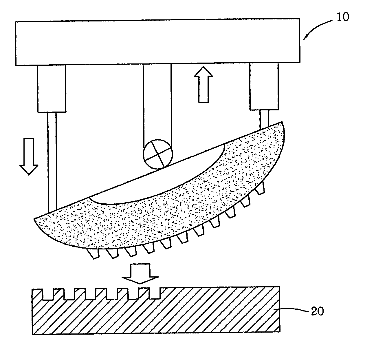
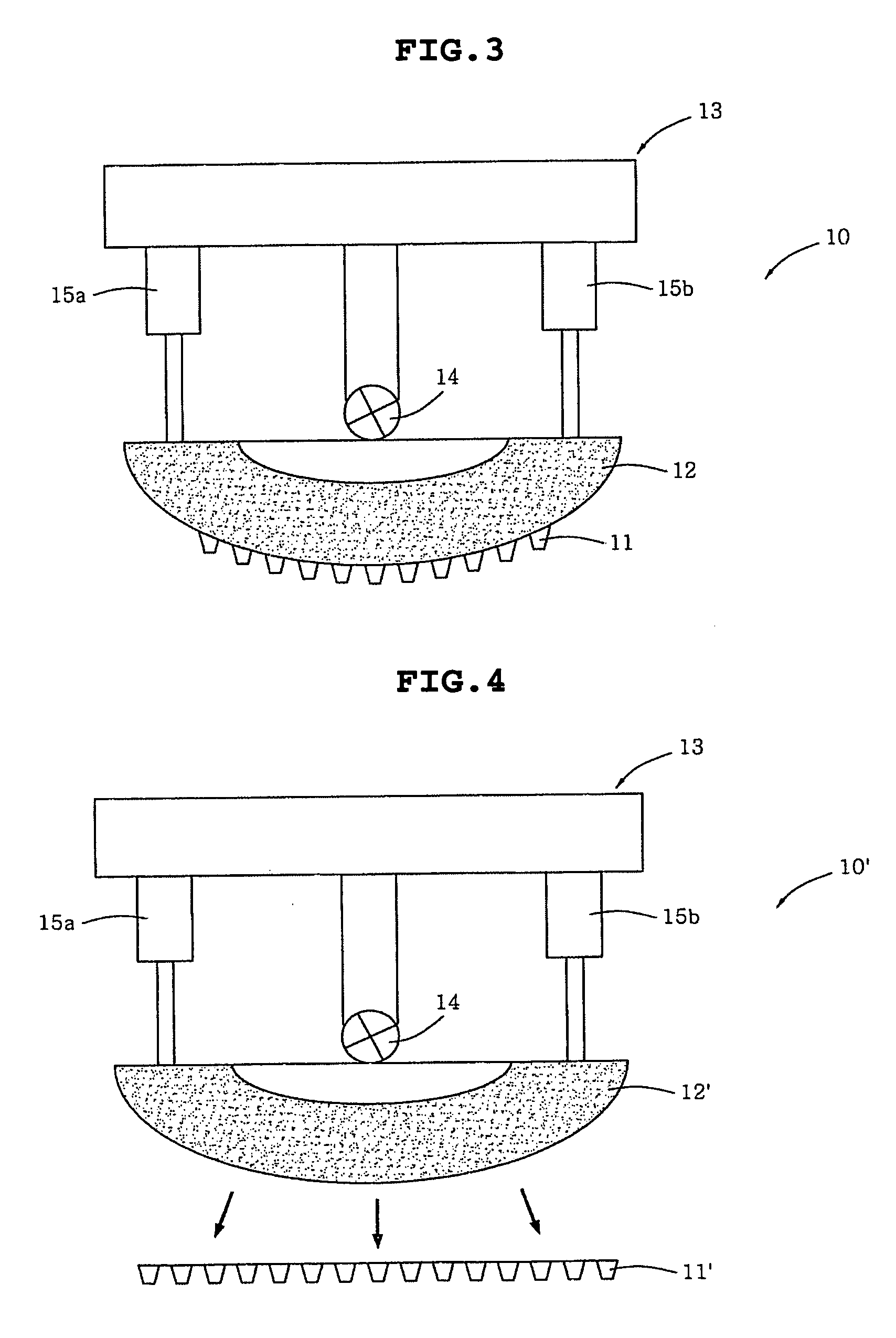
[0028]FIG. 3 illustrates an imprinting apparatus 10, according to an embodiment of the present invention.

[0029] As illustrated in FIG. 3, the imprinting apparatus 10 includes a semi-cylindrical body part 12 having a curved lower surface and a flat upper surface, and a pattern part 11 provided on the curved lower surface of the body part 12.

[0030] In addition, the imprinting apparatus 10 further includes a pressure part 13 for sequentially pressurizing the upper surface of the body part 12.

[0031] The pressure part 13 includes a first pressure rod 15a and a second pressure rod 15b for sequentially applying pressure to both sides of the body part 12 relative to a central shaft 14 of the body part 12. The pressurization by the first and second pressure rods 15a and 15b may be conducted using a known pressure device, such as a pneumatic pump or a hydraulic pump. ...


PUM

PropertyMeasurementUnit
sizeaaaaaaaaaa
temperatureaaaaaaaaaa
pressureaaaaaaaaaa

Abstract

The present invention relates to an imprinting apparatus, system and method. Specifically, the present invention relates to an imprinting apparatus, system and method, which can be applied to a large substrate, in which a substrate is aligned, imprinted through sequential pressurization by the imprinting apparatus to form a circuit pattern on the substrate and easily released from the imprinting apparatus.

Description

[0001] The present application claims priority under 35 U.S.C. §119 to Korean Patent Application No. 10-2005-0029027 filed on Apr. 7, 2005. The content of the application is incorporated herein by reference in its entirety. BACKGROUND OF THE INVENTION [0002] 1. Field of the Invention [0003] The present invention relates, generally, to an imprinting apparatus, system and method. More particularly, the present invention relates to an imprinting apparatus, system and method, which can be applied to a large substrate, in which a substrate is aligned, imprinted through sequential pressurization by the imprinting apparatus to form a circuit pattern on the substrate and easily released from the imprinting apparatus. [0004] 2. Description of the Related Art [0005] According to recent trend toward the fabrication of light, slim, short and small electronic products to be miniaturized, made thin, highly dense, packaged and personally portable, miniaturization and packaging of a printed circuit...

Claims


Application Information

Patent Timeline
Patent Type & Authority Applications(United States)
IPC IPC(8): B29C59/02
CPCB29C59/02B29C2043/463H05K3/0014H05K2203/0143H05K2201/09036H05K2203/0108H05K3/107A01D90/02B62B1/00
Inventor KWAK, JEONG BOKMAENG, IL SANGRA, SEUNG HYUN
Owner SAMSUNG ELECTRO MECHANICS CO LTD
Why Eureka
Try Eureka